Camera for monitoring utilizing power line communication

a power line communication and camera technology, applied in powerline communication applications, instruments, television systems, etc., can solve the problems of no original functions of the device, no power line communication can be also performed, and no monitoring area state during power stoppage can be known at all

Inactive Publication Date: 2005-08-02
ALPS ALPINE CO LTD
View PDF8 Cites 155 Cited by
  • Summary
  • Abstract
  • Description
  • Claims
  • Application Information

AI Technical Summary

Problems solved by technology

Therefore, when the supply of the electric power from the power line is interrupted by power stoppage, etc. in these devices, no original functions of the devices can be fulfilled and no power line communication can be also performed.
In particular, in the case of the camera for monitoring explained above, when the supply of the electric power is interrupted by the power stoppage, no state of a monitoring area during the power stoppage can be known at all.

Method used


Image

  • Camera for monitoring utilizing power line communication
  • Camera for monitoring utilizing power line communication
  • Camera for monitoring utilizing power line communication

Examples


Embodiment Construction

[0019]The embodiment modes of a camera for monitoring in the present invention will be explained in detail by the drawings. The construction of a system applying the present invention thereto may be set to the same as the case of the prior art explained by FIG. 3.

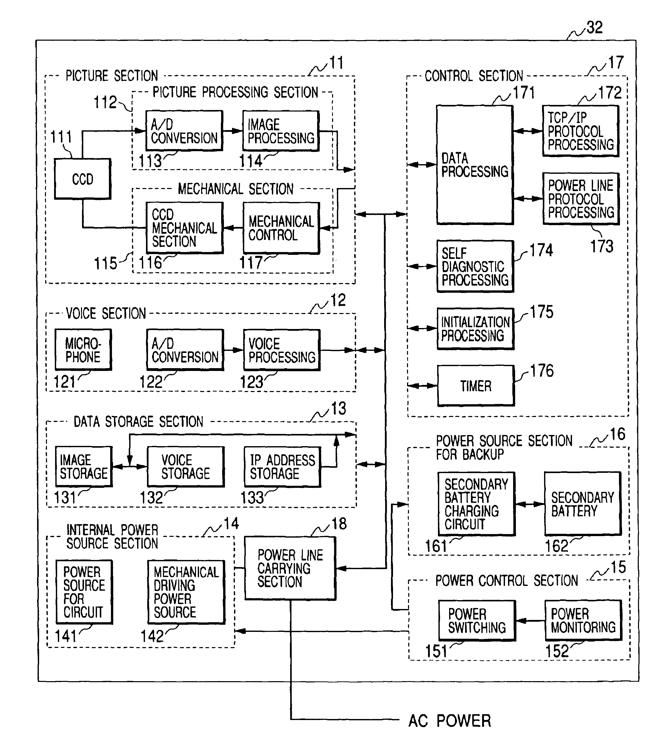
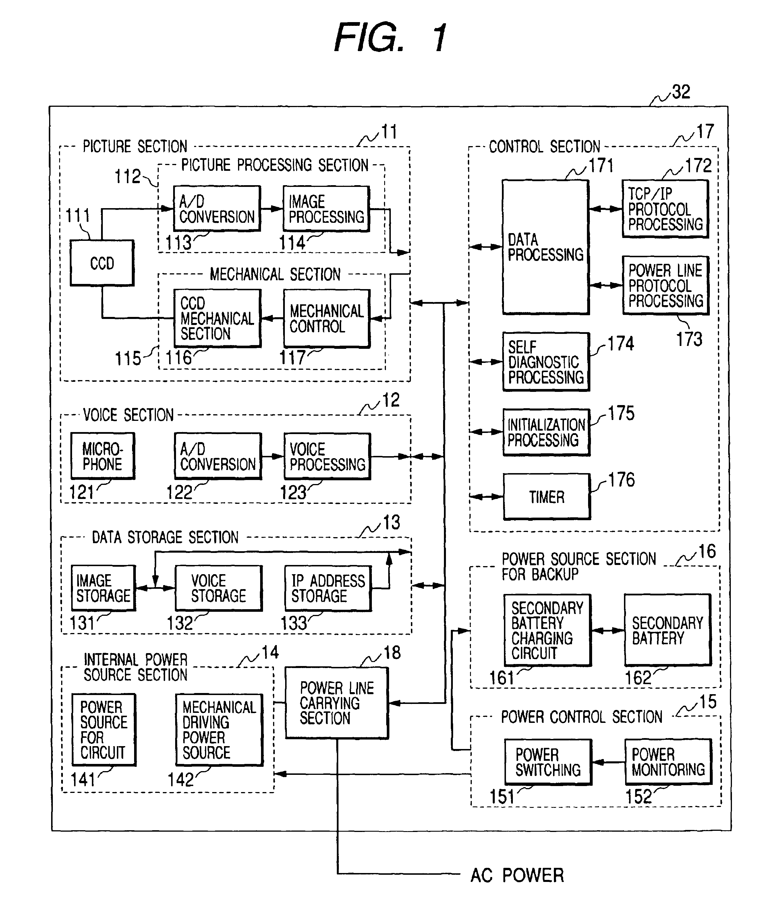
[0020]FIG. 1 is a block diagram showing the construction of a camera for monitoring in accordance with one embodiment mode of the present invention. In FIG. 1, reference numerals 11, 12 and 13 respectively designate a picture section, a voice section and a data storage section. Reference numerals 14, 15 and 16 respectively designate an internal power source section, a power control section and a power source section for backup. Reference numerals 17, 18 and 111 respectively designate a control section, a power line carrying section and a CCD element. Reference numeral 112 designates a picture processing section. Reference numerals 113, 122 designate A / D converting sections. Reference numerals 114, 115 and 116 respectively d...


PUM


Abstract

A power monitoring section detects the interruption of AC electric power from a power line, and switches operating power within a camera to power from a battery. A control section sets control of the camera to a different mode at the power stopping time. The operation is controlled to pick-up one static image at constant time intervals, and sequentially stores the static image to a data storage section. A voice section stops collecting sounds. The control section stops communication with a master set. When the AC electric power is restored the operating power is switched to the electric power from the power line. When a user utilizing the master set knows the restoration of the power, the user gives commands for reading image information stored during the power stoppage to the camera, and monitors the state during the interruption of the AC electric power.

Description

BACKGROUND OF THE INVENTION[0001]1. Field of the Invention[0002]The present invention relates to a camera for monitoring, and particularly relates to the camera for monitoring able to transmit a video signal to a master set by using power line communication (PLC).[0003]2. Description of the Related Art[0004]In recent years, a system having a power line communication function in in-home devices such as various kinds of home electric products, etc. is proposed within a home, etc. In this system, these in-home devices are monitored and controlled from a master set constructed by PC, etc. The above master set is accessed from the exterior through a public communication network. Thus, the in-home devices can be monitored and controlled from the exterior.[0005]FIG. 3 is a view schematically showing the construction of the monitoring control system of the in-home device using the PLC in the prior art. The system of the prior art will next be explained by FIG. 3. In FIG. 3, reference numera...

Claims


Application Information

Patent Timeline
Patent Type & Authority Patents(United States)
IPC IPC(8): G08B25/01G08B25/06H04N7/10H04N7/18H04N5/232H04B3/54
CPCG08B13/19634G08B13/19663G08B25/06H04N5/23203H04N7/108H04N7/186H04B2203/545H04B2203/5458H04N23/66
Inventor YOKOO, KENICHI
Owner ALPS ALPINE CO LTD
Why Eureka
Try Eureka