Reception antenna, core, and portable device

a technology of reception antennas and cores, applied in the direction of loop antennas, loop antennas with ferromagnetic cores, inductances, etc., can solve the problems of lowering communication performance and impossible communication, and achieve the effect of preventing interference among the antenna coils, enhancing the prevention of preventing the influence of stray capacitance in the reception antenna

Inactive Publication Date: 2005-08-02
DENSO CORP
View PDF8 Cites 51 Cited by
  • Summary
  • Abstract
  • Description
  • Claims
  • Application Information

AI Technical Summary

Benefits of technology

[0010]To achieve the above object, a reception antenna is provided with the following. Three antenna coils are disposed and their center axes intersect mutually orthogonally at an intersecting point. Each of them is symmetrical to the intersecting point. A core around which electric wire is wound is disposed for forming each of the three antenna coils. A first antenna coil of the three antenna coils is inwardly formed and a third antenna coil is outwardly formed. A second antenna coil is formed between the first and third antenna coils. The second antenna coil and one of the first and the third antenna coils constitutes a pair of selected antenna coils. A terminating end of winding electric wire of an inwardly-located antenna coil of the pair is connected with a starting end of winding electric wire of an outwardly-located antenna coil of the pair. This structure enables the reception antenna to be downsized and prevents interference among the antenna coils due to stray capacitance generated from an overlapping area between the antenna coils.
[0011]It is preferable that the other antenna coil that is excluded from the pair of the selected antenna coils and each of the pair of the selected antenna coils are overlapped with a space. Providing the space results in additionally enhancing prevention of the influence of the stray capacitance in the reception antenna.
[0012]Furthermore, a core for forming each of three antenna coils has a shape...

Problems solved by technology

At worst, the communication becomes impossible.
Closely disposing the plurality of the antenna coils in the limited volume...

Method used


Image

  • Reception antenna, core, and portable device
  • Reception antenna, core, and portable device
  • Reception antenna, core, and portable device

Examples


Embodiment Construction

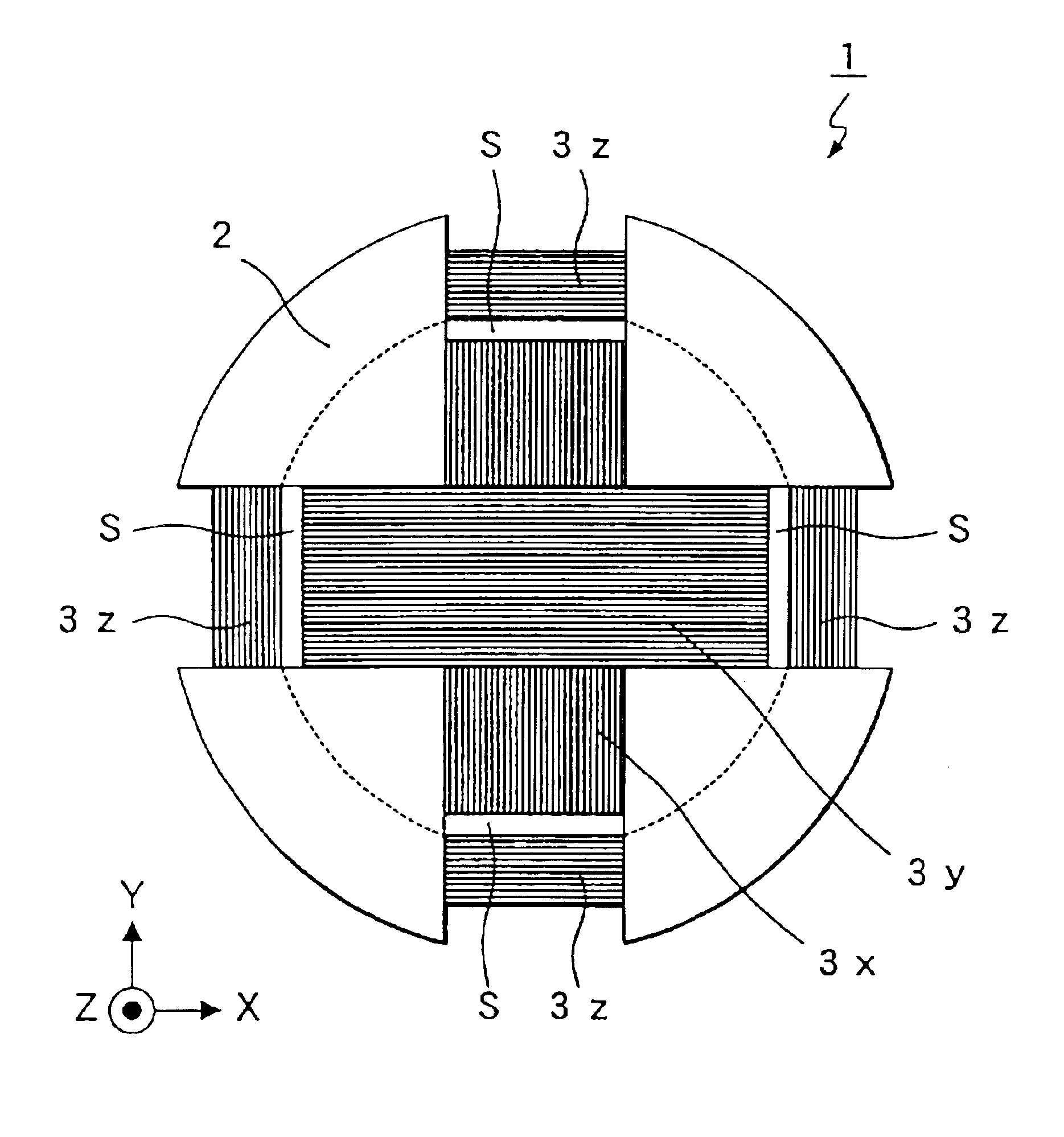
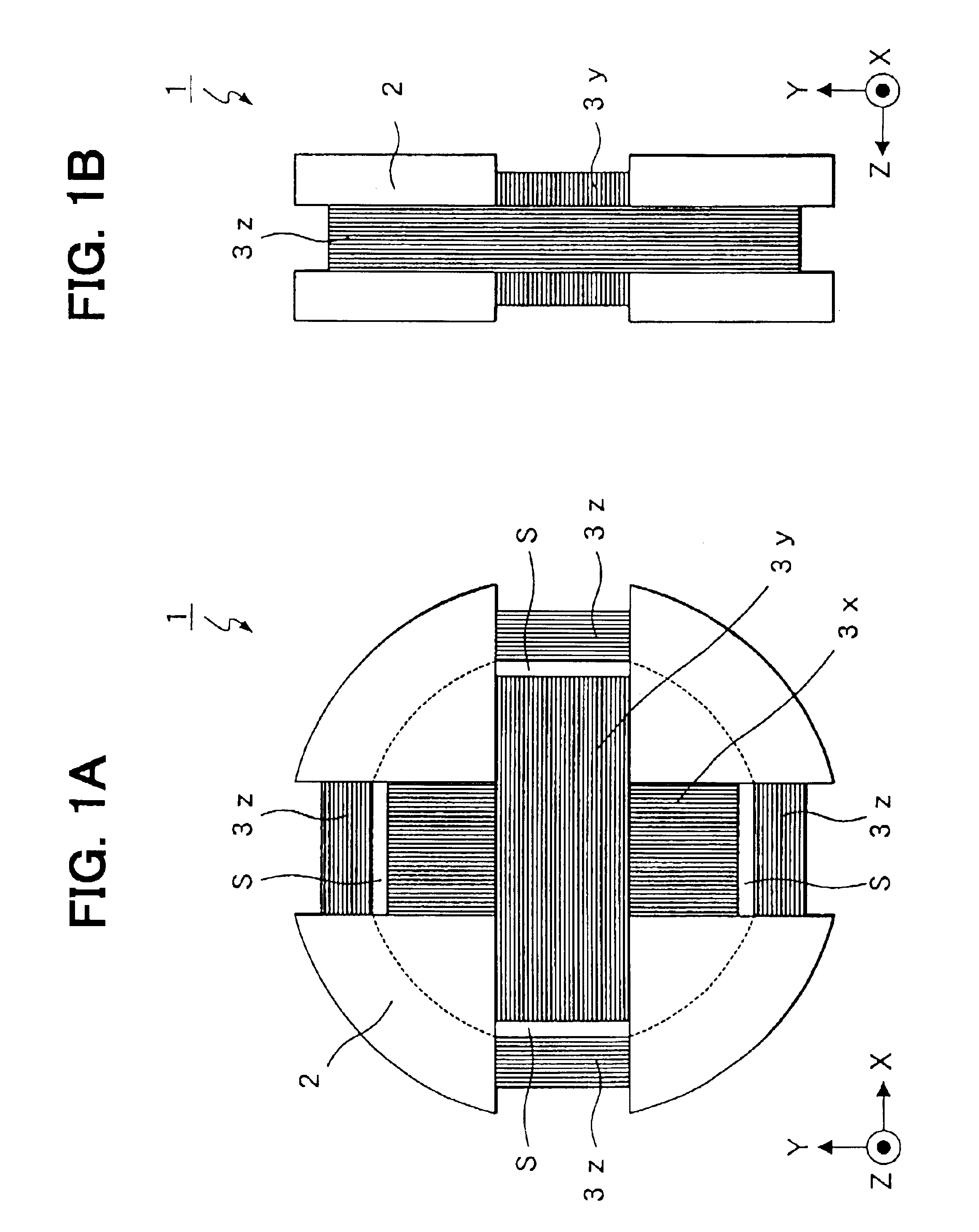
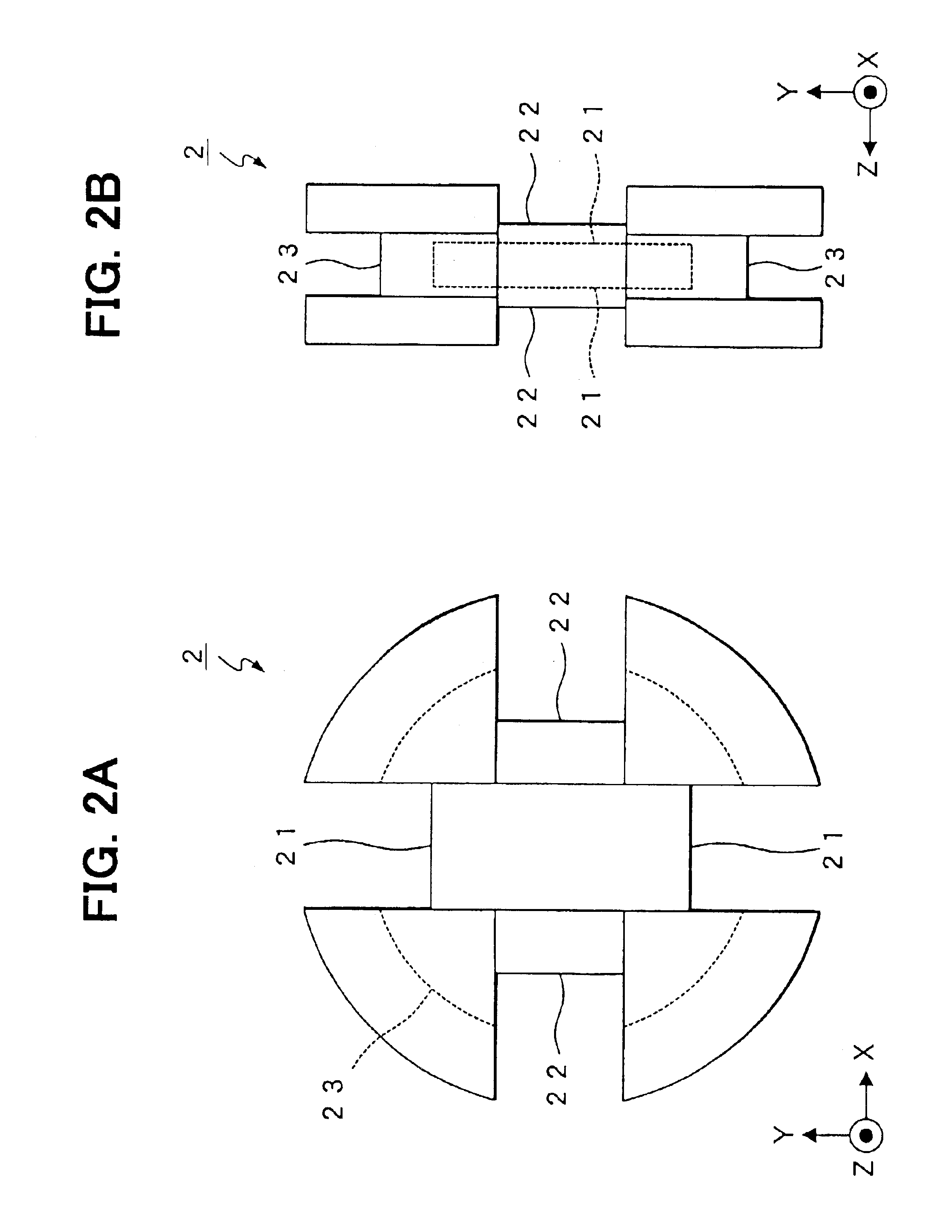
[0033]An embodiment of the present invention will be explained with figures. FIGS. 1A and 1B are a top and a side views showing structure of a three-axis integrated reception antenna (hereinafter referred to only “reception antenna”).

[0034]A reception antenna 1 of the embodiment is formed of a column-profiled ferrite core 2 and three antenna coils 3x, 3y 3z, each of which is formed by winding electric wire around the core 2. Each central axis of the three antenna coils 3x, 3y, 3z is mutually disposed orthogonally at a barycenter of the core 2, and each of the three antenna coils 3x, 3y, 3z is symmetrical with respect to the barycenter.

[0035]Here, a direction of the central axis of the core 2 is z direction. Two directions being orthogonal with each other in a sectional plane that is orthogonal to the central axis of the core 2 are X and Y directions. The antenna coil 3x is formed by winding electric wire around the core 2 with being centering on X direction. The antenna coil 3y is f...


PUM


Abstract

A reception antenna is formed of a column-profiled ferrite core and three antenna coils, each of which is formed by winding electric wire around the core. Each central axis of the three antenna coils is mutually disposed orthogonally at a barycenter of the core. Each of the three antenna coils is symmetrical with respect to the barycenter. A third antenna coil and each of a first antenna coil and a second antenna coil are overlapped with a space. The first antenna coil and the second antenna coil are overlapped with direct contact, where a starting end of the second antenna and a terminating end (outward end) of the first antenna is connected.

Description

CROSS REFERENCE TO RELATED APPLICATIONS[0001]This application is based on and incorporates herein by reference Japanese Patent Application No. 2002-162705 filed on Jun. 4, 2002.FIELD OF THE INVENTION[0002]The present invention relates to a reception antenna whose three antenna coils are mutually orthogonal, a core included in the reception antenna, and a portable device using the reception antenna.BACKGROUND OF THE INVENTION[0003]Conventionally, it is known that an electronic key system controls locking / unlocking of a vehicle door through communicating by wireless between an in-vehicle device mounted in a vehicle and an electronic key unique to the vehicle.[0004]In this electronic key system, the in-vehicle device periodically sends out a signal to the outside of the vehicle, for instance, when a key is not inserted into a key cylinder of the vehicle and furthermore all doors of the vehicle are locked. When a driver having an electronic key is near the vehicle, a response signal to ...

Claims


Application Information

Patent Timeline
IPC IPC(8): H01Q7/00H01Q1/32H01Q7/08H01Q7/06
CPCH01Q1/3241H01Q7/08H01F17/0033H01Q1/00
Inventor KITAHARA, TAKAHIDENAGAI, NOBUYOSHI
Owner DENSO CORP
Why Eureka
Try Eureka