Plant maintenance method and apparatus

a maintenance method and equipment technology, applied in the direction of instruments, nuclear elements, nuclear engineering, etc., to achieve the effect of recovery cost, recovery cost, and recovery cos

Inactive Publication Date: 2005-08-02
KK TOSHIBA
View PDF5 Cites 8 Cited by
  • Summary
  • Abstract
  • Description
  • Claims
  • Application Information

AI Technical Summary

Problems solved by technology

Classification of consequence of failure, however, requires experimental qualitative decision making, and hence has several drawbacks, for example, it does not necessarily involve quantitative evaluation.

Method used


Image

  • Plant maintenance method and apparatus
  • Plant maintenance method and apparatus
  • Plant maintenance method and apparatus

Examples


first embodiment

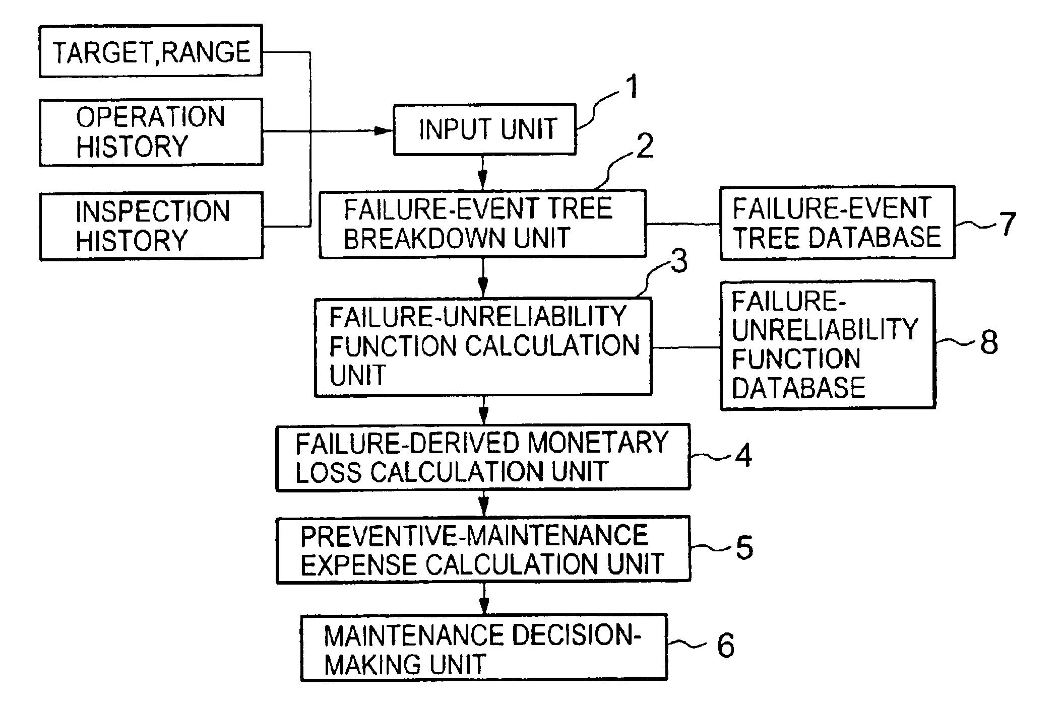
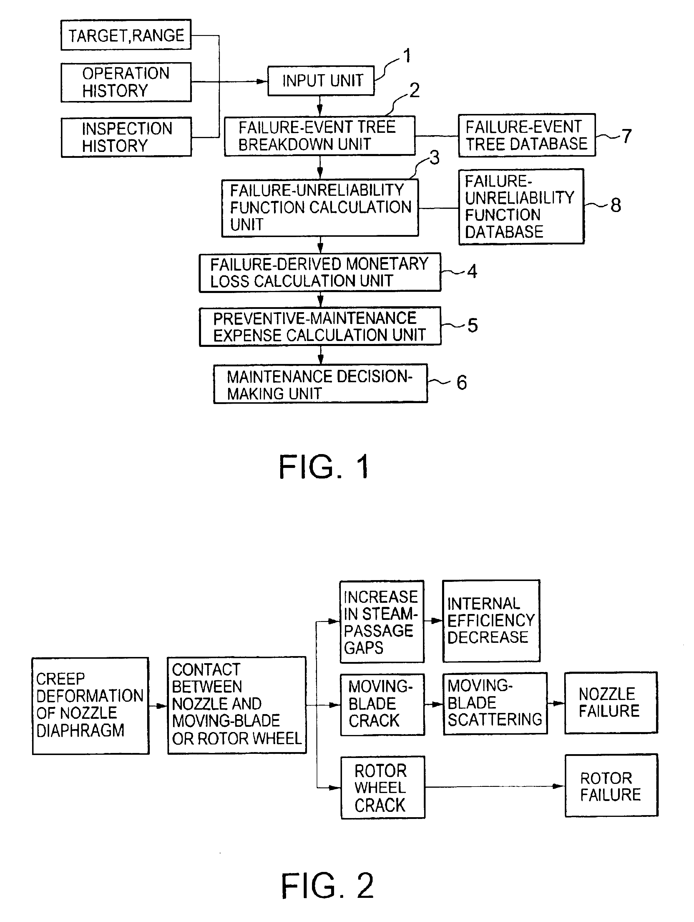
[0034]FIG. 1 shows a block diagram of a first embodiment according to the present invention. A plant-maintenance apparatus incorporates an input unit 1, a failure-event tree breakdown (FETB) unit 2, a failure-unreliability function calculation (FUFC) unit 3, a failure-derived monetary loss calculation (FDMLC) unit 4, a preventive-maintenance expense calculation (PMEC) unit 5 and a maintenance decision-making (MDM) unit 6.

[0035]Entered via the input unit 1 are targets and ranges or a list of plant component parts to be maintained, an operation history such as operation hours and operation-startup / shutdown times and an inspection history including inspection data on failures, damage, degradations and their indications. Disclosed below are operations of the first embodiment for inspection of falling-down of a nozzle diaphragm of a steam-turbine.

[0036]A steam-turbine nozzle diaphragm could suffer from creep deformation due to steam-pressure differences and hence fall down behind (toward...

second embodiment

[0056]FIG. 7 shows a block diagram of the maintenance apparatus according to the present invention. Elements shown in FIG. 7 the same as or analogous to elements shown in FIG. 1 are referenced by the same numerals.

[0057]With this embodiment, the apparatus further provided with an inspection-priority item selection (IPIS) unit 9 configured to select an inspection item. Preferably, the IPIS unit 9 selects an inspection item that can be inspected without disassembling the equipment (e.g., turbine) based on data on targets and ranges to be maintained entered via the input unit 1. In this embodiment, the IPIS unit 9 selects the erosion of the first-stage nozzle blade as the inspection item, which is the summit event in the failure-event tree.

[0058]As shown in the failure-event tree of FIG. 8 in which the nozzle-blade erosion is the summit event, a strainer or other parts such as valves located upstream of the first-stage nozzle erode when the first-stage nozzle blade erodes (with a littl...

third embodiment

[0068]FIG. 13 shows a block diagram of the maintenance apparatus according to the present invention. Elements shown in FIG. 13 the same as or analogous to elements shown in FIG. 1 are referenced by the same numerals.

[0069]With this embodiment, the maintenance apparatus further provided with a monitoring-item selection (MIS) unit 13 configured to select a monitoring item (i.e., an item to be monitored). Preferably, the MIS unit 13 selects a monitoring item that can be monitored without halting the operation of the plant based on data on targets and ranges to be maintained entered via the input unit 1. In this embodiment, the MIS unit 13 select the vibration of a turbine shaft as the monitoring item, which is an intermediate, resultant failure event expected from the summit event in the failure event tree.

[0070]If summit failure event is erosion of the steam-turbine nozzle blades, it is impossible to directly monitor the summit event, namely the condition of the nozzle blades, while t...


PUM


Abstract

An apparatus for maintaining plant equipment incorporates an input unit to receive information on targets and ranges of plant equipment to be maintained and a failure-event tree breakdown unit to perform tree-breakdown on failures to be expected from events to be inspected. A failure-unreliability function calculation unit calculates unreliability of each item in failure-event tree breakdown and a failure-derived monetary loss calculation unit multiplies each unreliability and a cost of recovery from each event in accordance with the failure-event tree breakdown. A preventive maintenance expense calculation unit calculates preventive maintenance expenses for preventing failure events and a maintenance decision-making unit decides maintenance timing and technique through comparison between the recovery cost and the preventive maintenance expense.

Description

CROSS REFERENCE TO RELATED APPLICATION[0001]This application is based upon and claims the benefit of priority from the prior Japanese Patent Application No. 2002-106666, filed on Apr. 9, 2002, the entire contents of which are incorporated herein by reference.BACKGROUND OF THE INVENTION[0002]The present invention relates to plant-maintenance apparatus and method for maintaining plant equipment such as steam turbines for thermal power plants.[0003]Increase in the number of plants such as thermal power plants used for long years has demanded maintenance at low cost but with no failures. Risk-based maintenance (RBM) has been recently introduced as one of the solutions to match the demands. A known RBM is to decide maintenance priority allocations based ranking in the order of combinations of classified plant-equipment failure rates and consequence of failure, such as, disclosed by Kihara et el., in Piping Technology, pages 76 to 79, issued in December, 2000.[0004]Classification of conse...

Claims


Application Information

Patent Timeline
Patent Type & Authority Patents(United States)
IPC IPC(8): G06Q10/00G05B23/02G06Q50/10G06Q50/00
CPCG06Q10/06
Inventor FUJIYAMA, KAZUNARIFUJIWARA, TOSHIHIROSAITO, KAZUHIROHIRAWAWA, TAIJINAGAI, SATOSHIKICHISE, HITOSHIOKAZAKI, MITSUYOSHIKODAMA, HIROTSUGUASATSU, SEIICHIMINOWA, MASANORIIWAHASHI, TAKAYUKIHARADA, SHIGERUSUDO, MAMORUISHII, FUMIHARU
Owner KK TOSHIBA
Why Eureka
Try Eureka