Microarchitecture of an arithmetic unit

Active Publication Date: 2005-08-02
STMICROELECTRONICS SRL
View PDF3 Cites 37 Cited by
  • Summary
  • Abstract
  • Description
  • Claims
  • Application Information

AI Technical Summary

Benefits of technology

[0026]FIG. 1 is a schematic diagram showing a conventional microarchitecture of an arithmetic unit with two cascaded adders;
[0027]FIG. 2 is a schematic diagram showing an improved microarchitecture of an arithmetic unit with an exemplary embodiment of a circuit for deter

Problems solved by technology

One problem of the microarchitecture that has just been described is that the two cascaded adders provide a non-optimized computation time which is especially disadvantageous as the operands to be processed are encoded on many bits.
With two cascaded adders, the data pa

Method used


Image

  • Microarchitecture of an arithmetic unit
  • Microarchitecture of an arithmetic unit
  • Microarchitecture of an arithmetic unit

Examples


Embodiment Construction

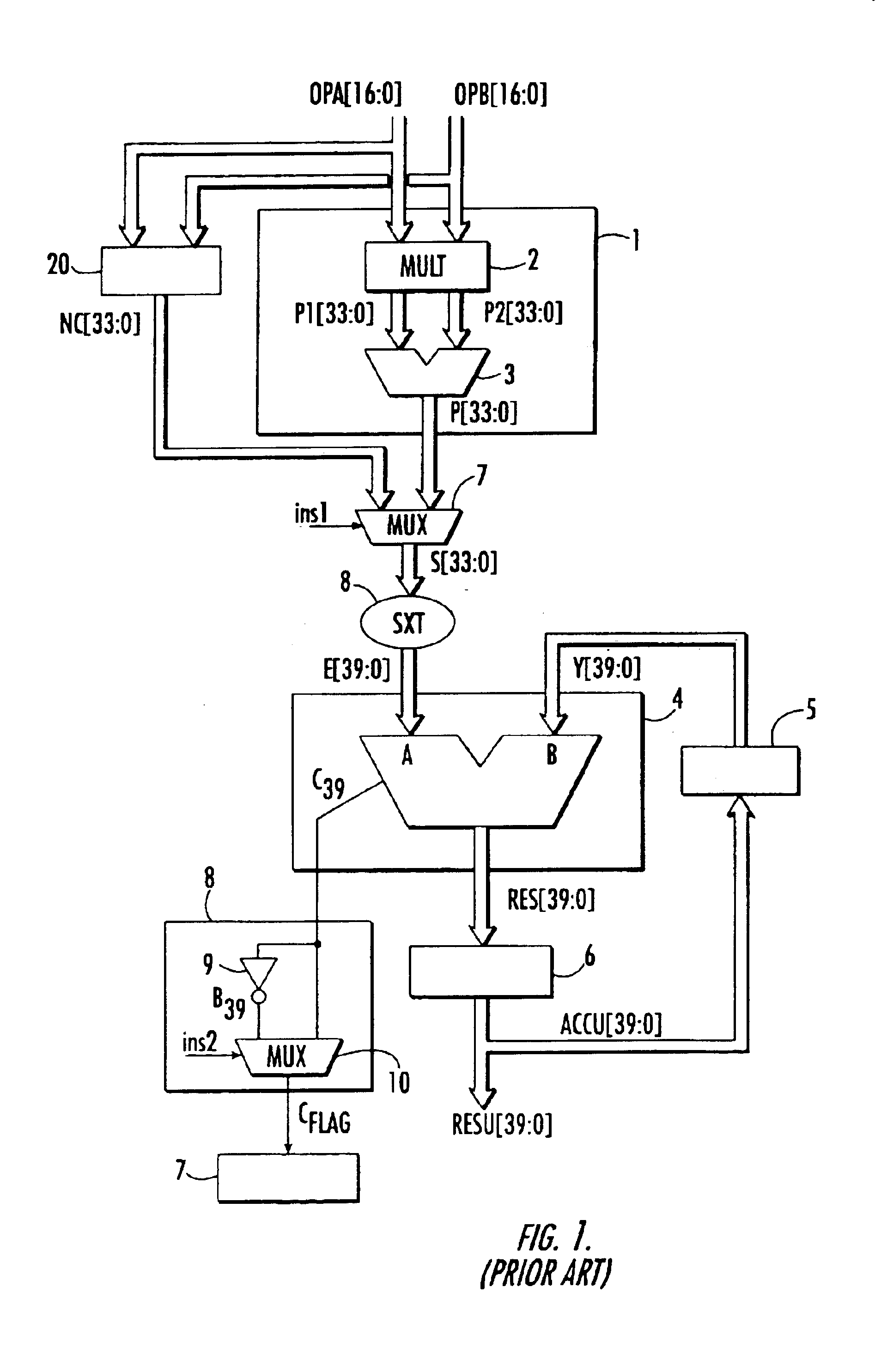
[0029]FIG. 1 shows a conventional arithmetic unit used especially to carry out multiplication-accumulation operations. In the example, it can also be used to carry out operations of accumulation of double precision numbers via the concatenation circuit. In this microarchitecture, the arithmetic unit has a multiplier 1 with two operands OPA, OPB applied to the inputs of the arithmetic unit. This multiplier has a circuit 2 for the computation of the partial products P1 and P2 of the input operands followed by an adder 3 that outputs the result P of this multiplication, the format of this result being double the format of the input operands.

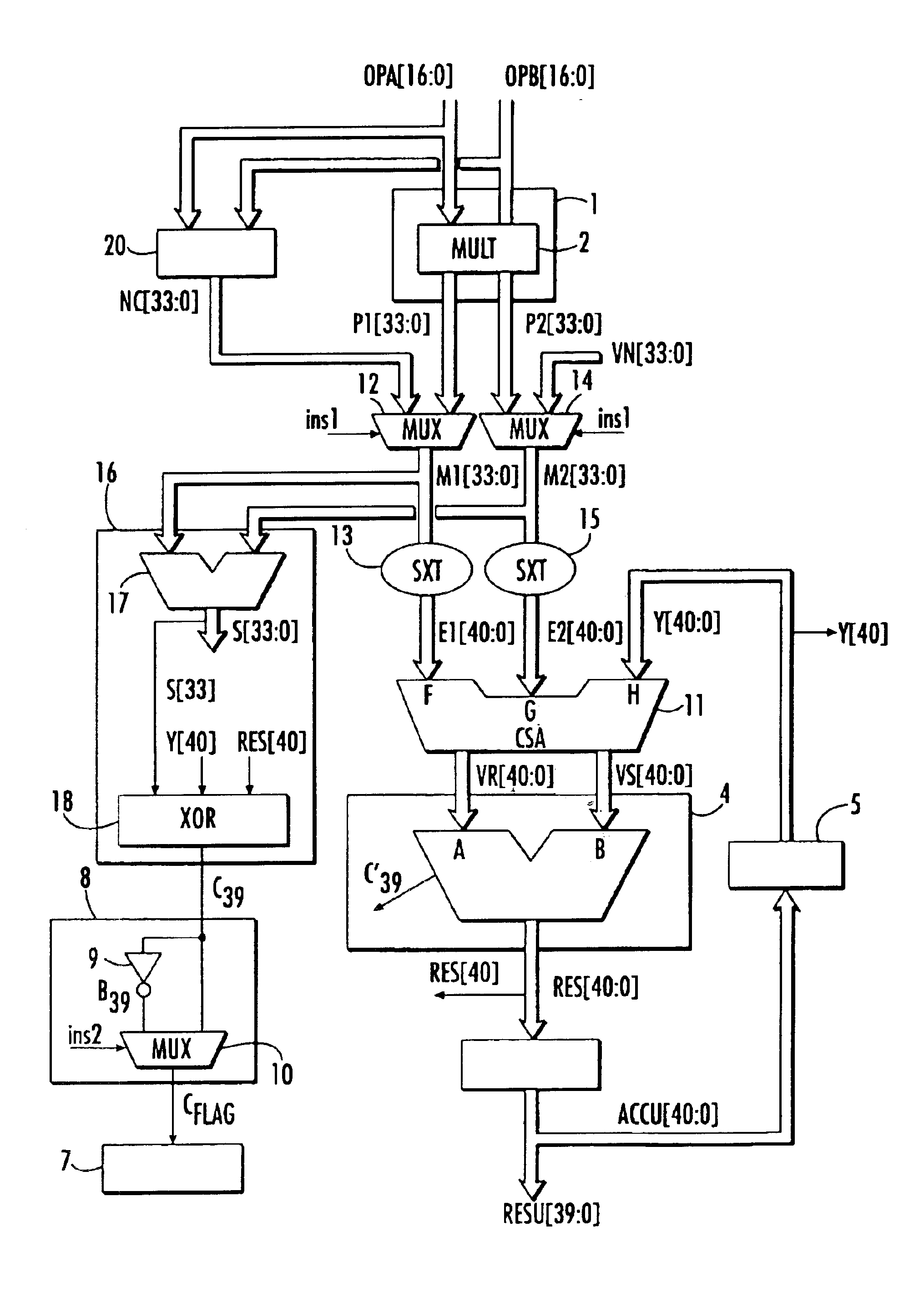
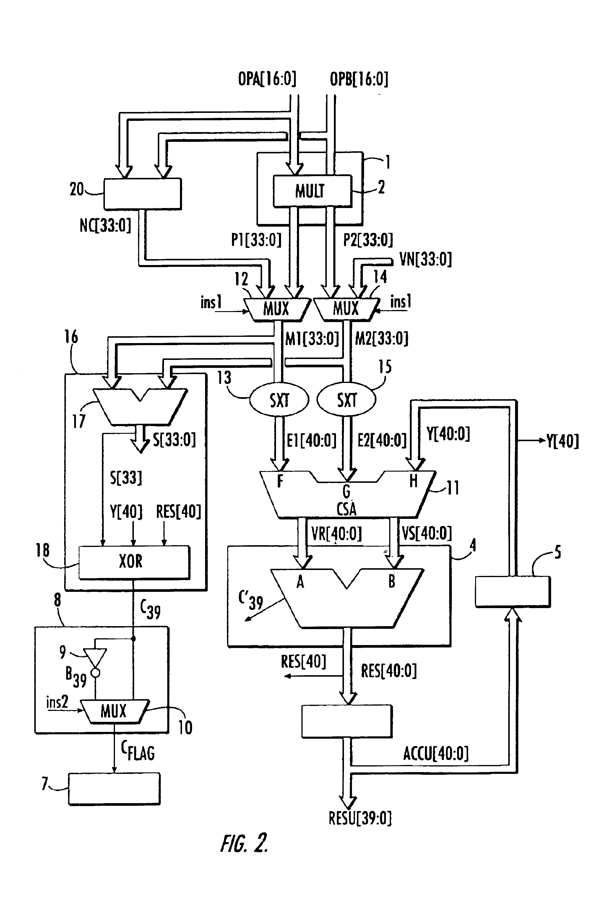
[0030]In the example, this arithmetic unit also has a concatenation circuit 20 for the concatenation of the two input operands OPA and OPB. It outputs a concatenated number NC, whose format is twice the format of the input operands. Either of these results P or NC is applied to a first input A of an adder 4. The other input B of the adder receives t...


PUM


Abstract

The microarchitecture of the arithmetic unit includes two cascaded N bit adders to provide an N bits result in an accumulator. The arithmetic unit also includes a carry save adder, followed by an adder, which, along with the accumulator, are extended to N+1 bits. A circuit for determining the output carry value associated with the result is also provided.

Description

FIELD OF THE INVENTION[0001]The present invention relates to the field of arithmetic units, and, more particularly, to the microarchitecture of arithmetic units.BACKGROUND OF THE INVENTION[0002]Arithmetic units are used especially in programmable integrated circuits such as microprocessors or microcontrollers. They can be used to carry out a number of arithmetic operations on operands. A well-known field of application is digital signal processing, to apply filters, transfer functions, transforms etc.[0003]One arithmetic operation, commonly used for the different processing operations, is known as the multiplication-accumulation operation in which a sum of products is computed. If two input operands are called A and B and the contents of an accumulator are called Y, this operation is used to compute: RES=A×B+Y. This arithmetic operation conventionally requires an accumulator to contain the new result RES, which will be used at the next iteration, a multiplier to which the two input ...

Claims


Application Information

Patent Timeline
IPC IPC(8): G06F7/544G06F7/50G06F7/48G06F7/509
CPCG06F7/5095G06F7/5443
Inventor DUBORGEL, OLIVIER
Owner STMICROELECTRONICS SRL
Why Eureka
Try Eureka