
Two stage punch press actuator with output drive shaft position sensing

a technology of output drive shaft and actuator, which is applied in the direction of presses, metal working devices, manufacturing tools, etc., can solve the problems of double strikes, operator risk, and traditional mechanical actuators that have a number of problems in their operation, so as to reduce the potential for injury or damage

Inactive Publication Date: 2005-08-09
PCPS PARTNERSHIP
View PDF33 Cites 7 Cited by
  • Summary
  • Abstract
  • Description
  • Claims
  • Application Information

AI Technical Summary

Benefits of technology

[0017]We have invented an improvement to punch presses and other devices such as power operated clamps, which dramatically reduces the potential for injury or damage. Instead of trying to prevent the operator from placing himself within the zone of

Problems solved by technology

We find that traditional mechanical actuators have a number of problems in their operation.
Among the problems are double strikes, faulty tool alignment, and operator risk.
Double strikes for a mechanical press arise when a clutch improperly or unexpectedly applies force to the drive rod to mate the punch with the die without deliberately engaging the clutch.
Typically, double strikes occur as the result of wearing or faulty adjustment of the clutch parts.
Punch press clutches transfer large amounts of force and operate in dirty and otherwise hostile environments, so it is not surprising that the clutch mechanisms deteriorate with time.
And of course unseen and catastrophic failure of critical parts can also lead to double strikes.
Double strikes have the potential to be dangerous.
If the operator's hand is between the punch and die for the purpose of removing the finished workpiece from the die, a double strike may smash the hand with obvious potential for serious injury.
A double strike in this situation of course spoils the finished workpiece or workpiece blank, and may even damage the tooling.
Faulty tool alignment is a situation where the punch and die do not properly align.
This usually also arises from wear or poor maintenance.
The result is potentially to damage or even destroy the punch or die, or perhaps to damage the workpiece.
Tooling under high loads has even b

Method used


Image

  • Two stage punch press actuator with output drive shaft position sensing
  • Two stage punch press actuator with output drive shaft position sensing
  • Two stage punch press actuator with output drive shaft position sensing

Examples


Embodiment Construction

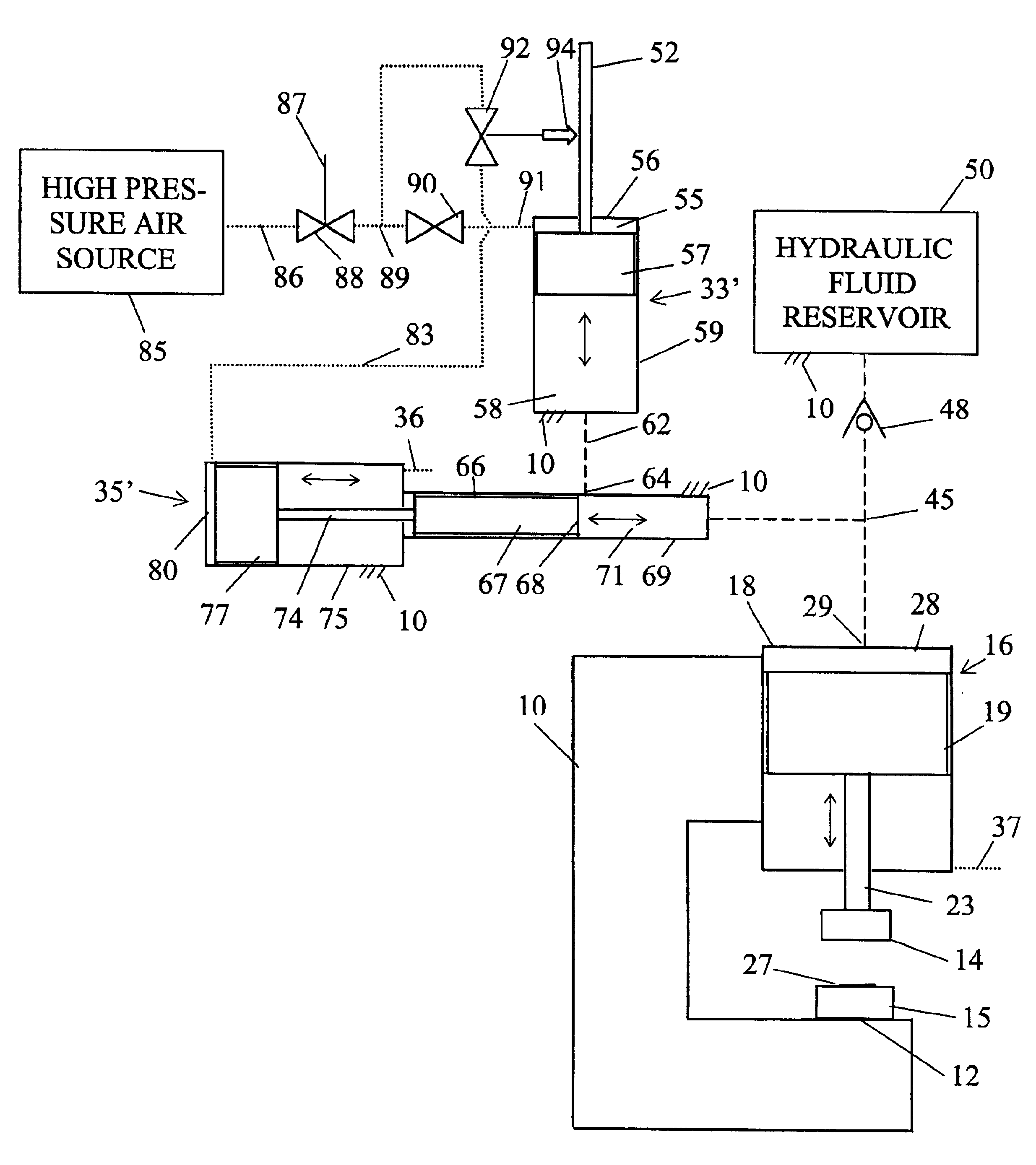
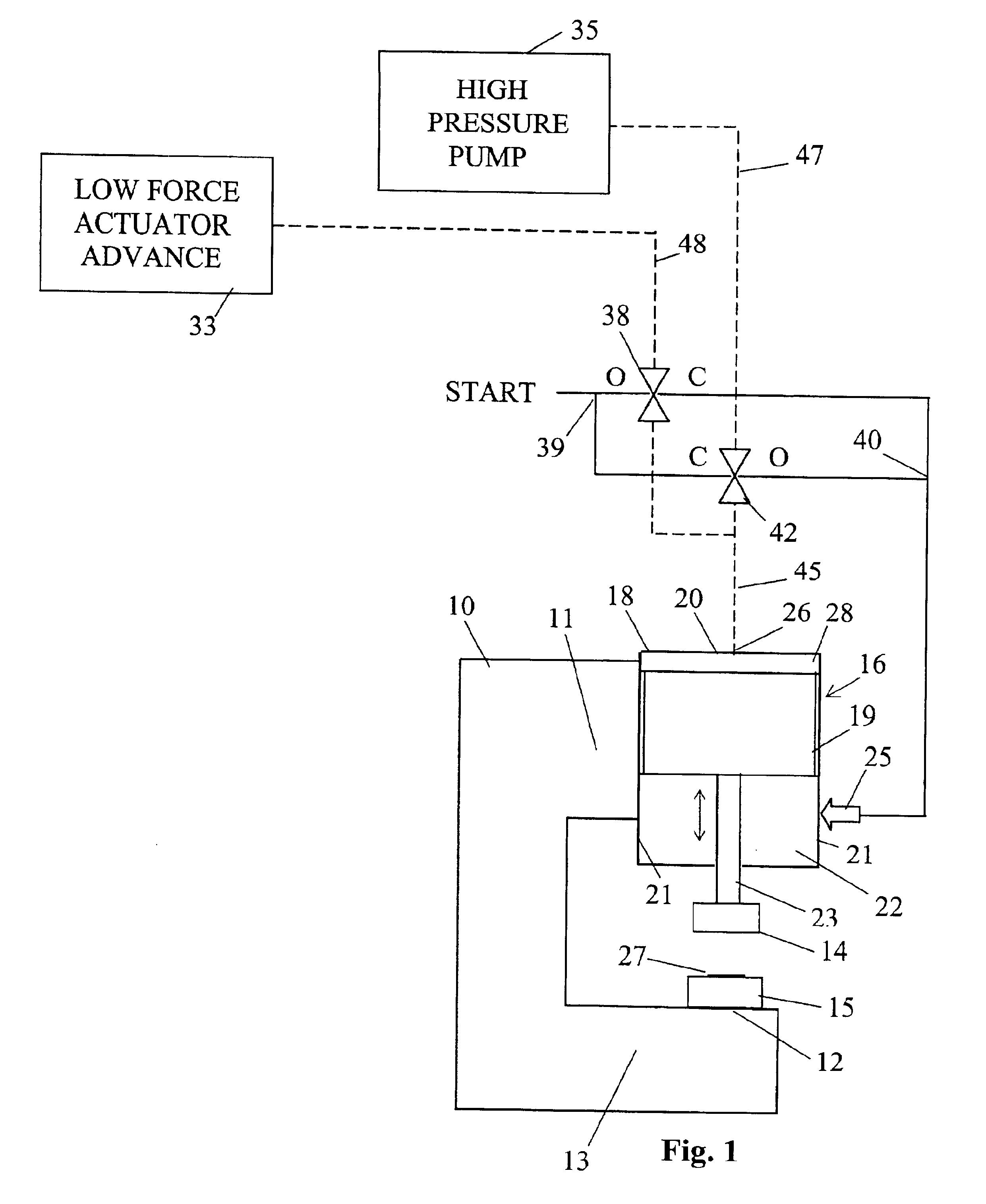
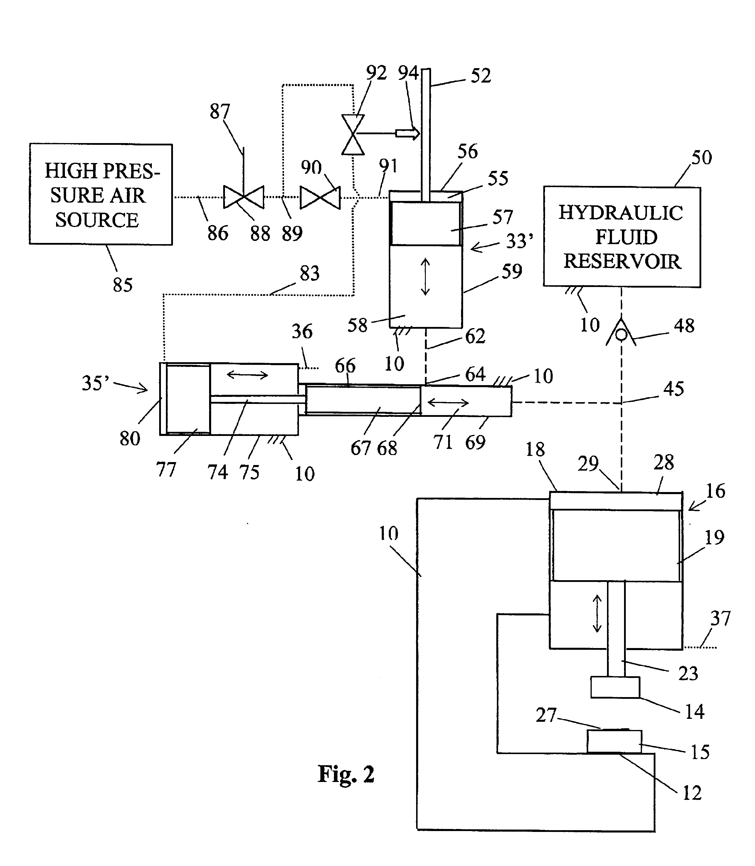
[0034]The invention as shown in FIG. 1 is substantially simplified as compared to a commercial embodiment. Referring to FIG. 1, the punch press shown there includes a C-shaped frame 10 including an upper arm 11 and a lower arm 13. Lower arm 13 defines on its upper surface a table 12 for supporting a tooling half or die 15. During an operating cycle of the press, a workpiece 27 to be formed rests on die 15. Upper arm 11 supports an actuator element comprising a hydraulic cylinder 16 which is a part of a complete actuator assembly. Cylinder 16 comprises a housing 18 with an internal cylindrical (and usually circular cross section) bore 22 defined by cylindrical walls 21 and closed by an end wall 20. A piston 19 is mounted to slide along a linear piston path within walls 21 as suggested by the double arrow shown. Piston 19 has a fluid-tight fit with walls 21 while sliding along the piston path. Piston 19 along with end wall 20 and side walls 21 collectively define a pressure chamber 28...


PUM

PropertyMeasurementUnit
Forceaaaaaaaaaa
Pressureaaaaaaaaaa
Distanceaaaaaaaaaa

Abstract

A press for forming a workpiece with a tooling set includes an actuator assembly carrying a movable half or punch of the tooling set and having a two phase operation. In the first phase the actuator provides relatively low force in moving the punch to an intermediate position in close proximity to the workpiece. A sensor detects the position of the punch, and when the punch reaches the intermediate position provides a continue signal. The second phase of actuator operation is conditioned on occurrence of the continue signal, and uses normal high force to press the movable tooling half against the workpiece to complete the operation. The low force first phase allows obstructions of any kind to stop movement of the punch during the first phase before high force applied to the actuator may cause damage or injury to the obstruction. In a preferred embodiment the actuator assembly has hydraulic operation.

Description

[0001]The present application is a division of application Ser. No. 09 / 517,926, filed on Mar. 3, 2000, entitled TWO STAGE PUNCH PRESS ACTUATOR WITH OUTPUT DRIVE SHAFT POSITION SENSING, now U.S. Pat. No. 6,418,824, issued Jul. 16, 2002.BACKGROUND OF THE INVENTION[0002]Punch or stamping presses are a staple of manufacturing operations for products formed from workpieces such as metal sheets, rods, bars, etc. With properly designed tooling sets, punch presses can be used for a variety of manufacturing process operations including cutting, forming, drawing, shaping, and assembling. Punch presses come in sizes ranging from a meter or less in height to several meters in height, and can develop force ranging from hundreds to many thousands of kilograms.[0003]The structure of a punch press includes a frame with a table and with a drive rod or shaft mounted on the frame. Force applied to the rod causes the rod to translate toward and away from the table. The table supports a fixed half of th...

Claims


Application Information

Patent Timeline
IPC IPC(8): B21D28/02B21D28/00B21D28/20B30B15/28B30B15/16
CPCB21D28/002B21D28/20B30B15/161B30B15/281B30B15/285Y10S83/01Y10T83/04Y10T83/089Y10T83/175Y10T83/8719Y10T83/8735Y10T83/8858Y10T83/886Y10T83/8864Y10T83/9423
Inventor DUGGINS, TERRENCE P.HUGHES, ROBERT L.SCHWARZ, EDWARD L.
Owner PCPS PARTNERSHIP
Learn More