
Bumper with crash absorbing element

Inactive Publication Date: 2005-08-09
PEGUFORM
View PDF36 Cites 21 Cited by
  • Summary
  • Abstract
  • Description
  • Claims
  • Application Information

AI Technical Summary

Benefits of technology

[0018]One aspect of the invention is to provide an attachment part at a bumper which acts as a crash absorbing element and forms unitary part of the bumper, for the purpose of absorbing crashes up to 4 km / h in the elastic range, and absorbing crashes up to 15 km / h by being deformable in such a way as to prevent the transmission of forces to the front end beam.

Problems solved by technology

Although this extruded profile fulfills all legal requirements prescribed in regulation EWG96 / 76 EG for the solid wall tests, the bumper disclosed in DE 197 44 274A1 both, that is, the extruded profile as well as the bumper mounted thereon are necessary for its functioning and requires assembly of at least two parts and thus resulting in a comparatively high overall weight.
As a consequence higher costs for replacement or repair are experienced, since any impact, even a low speed impact, may cause damages to the bumper as well as the bumper beam.
For production-technical reasons it is not possible, to manufacture unitary bending beams and crash absorbing elements.
Thus, at a normal drive speed, any impact will certainly be absorbed through the bending beam and the deformation elements, however the production of the bending beams is rather complex due to the additional production steps of assembling the shells.
In addition, the bending beam is made of metal and exhibits no elasticity, so that for even small impacts an elastic yielding cannot be realized.
Accordingly, when the bumper cannot deform in an elastic manner, there subsists the danger of damage to the bumper even upon very small impact.
Whereas damage of this type may not always render the bumper unsuitable for use, it spoils the optical impression of the vehicle.
Thus, due to the inferior wall thickness of the crash absorbing elements, the transverse carriers will buckle or fail before the transverse beam deforms in a three-dimensional manner with a definite impact force.
However, the number of single parts still exceeds the number of parts disclosed in the previously discussed prior art.
The bumper beam itself is not a unitary piece but is made from profiles that are assembled from four plates, which requires for a considerable number of production steps.

Method used


Image

  • Bumper with crash absorbing element
  • Bumper with crash absorbing element
  • Bumper with crash absorbing element

Examples


Embodiment Construction

[0037]Throughout all the Figures, same or corresponding elements are generally indicated by same reference numerals.

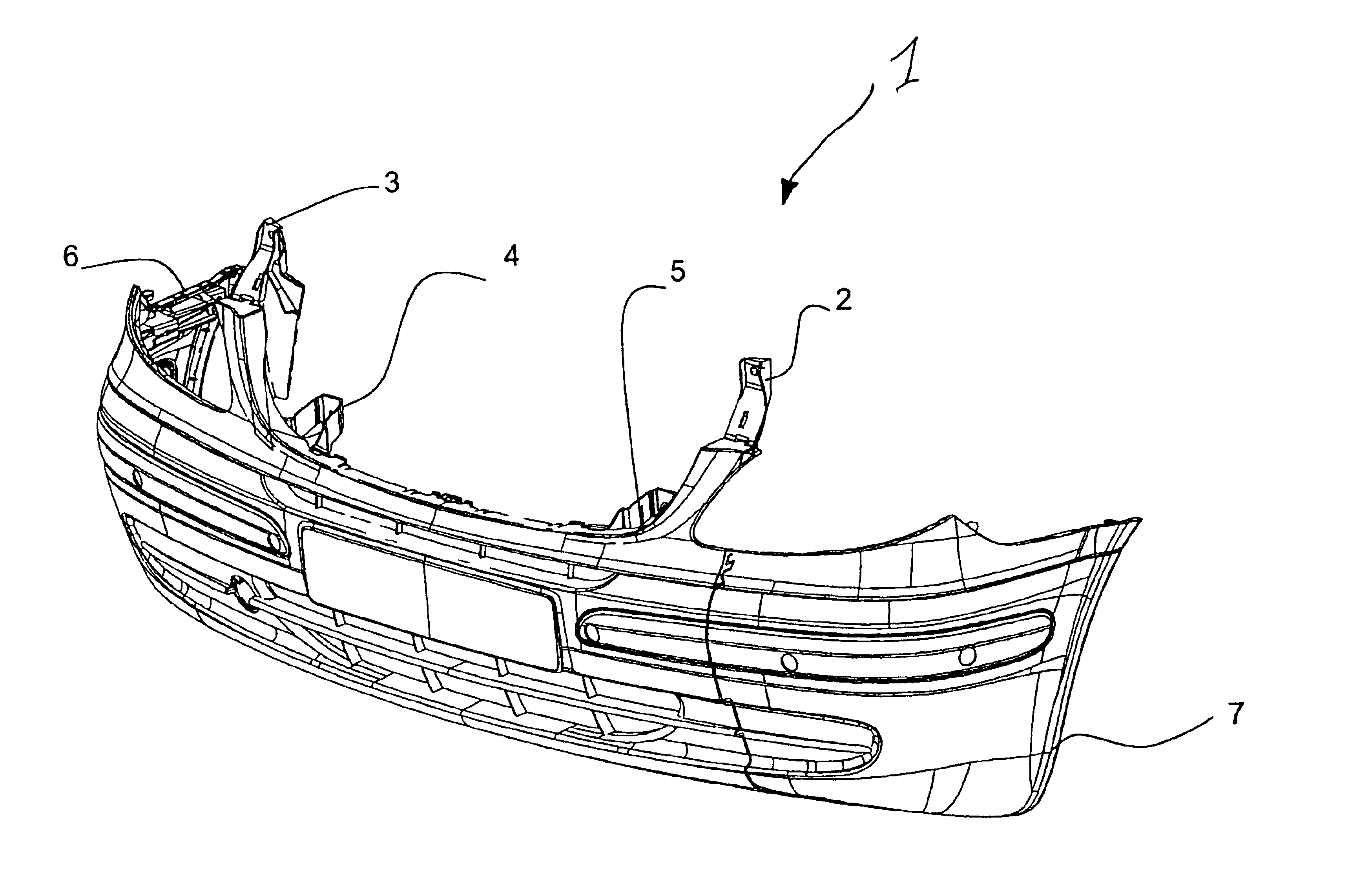
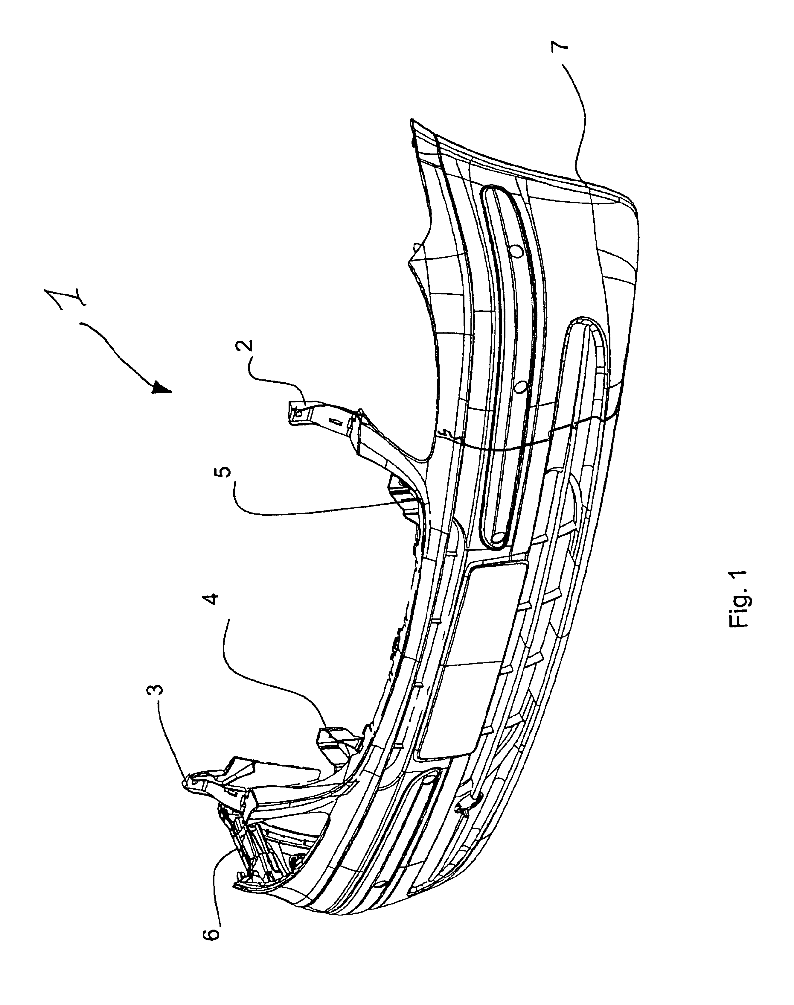
[0038]Turning now to the drawing, and in particular to FIG. 1, there is shown a bumper 1 in perspective view. The bumper 1 is releasably connected at attachment parts 2, 3, 4, 5 to the vehicle carrying structure (not represented). Additional attachment elements may be provided at the side flanges 6, 7 in order to attach the bumper in its position relative to other vehicle parts and to observe the appropriate tolerances and gaps. It is understood that the function of the bumper is not limited to the absorption of shocks, but can incorporate brackets for lighting fixtures, sensors and their cables as well a license plate or similar.

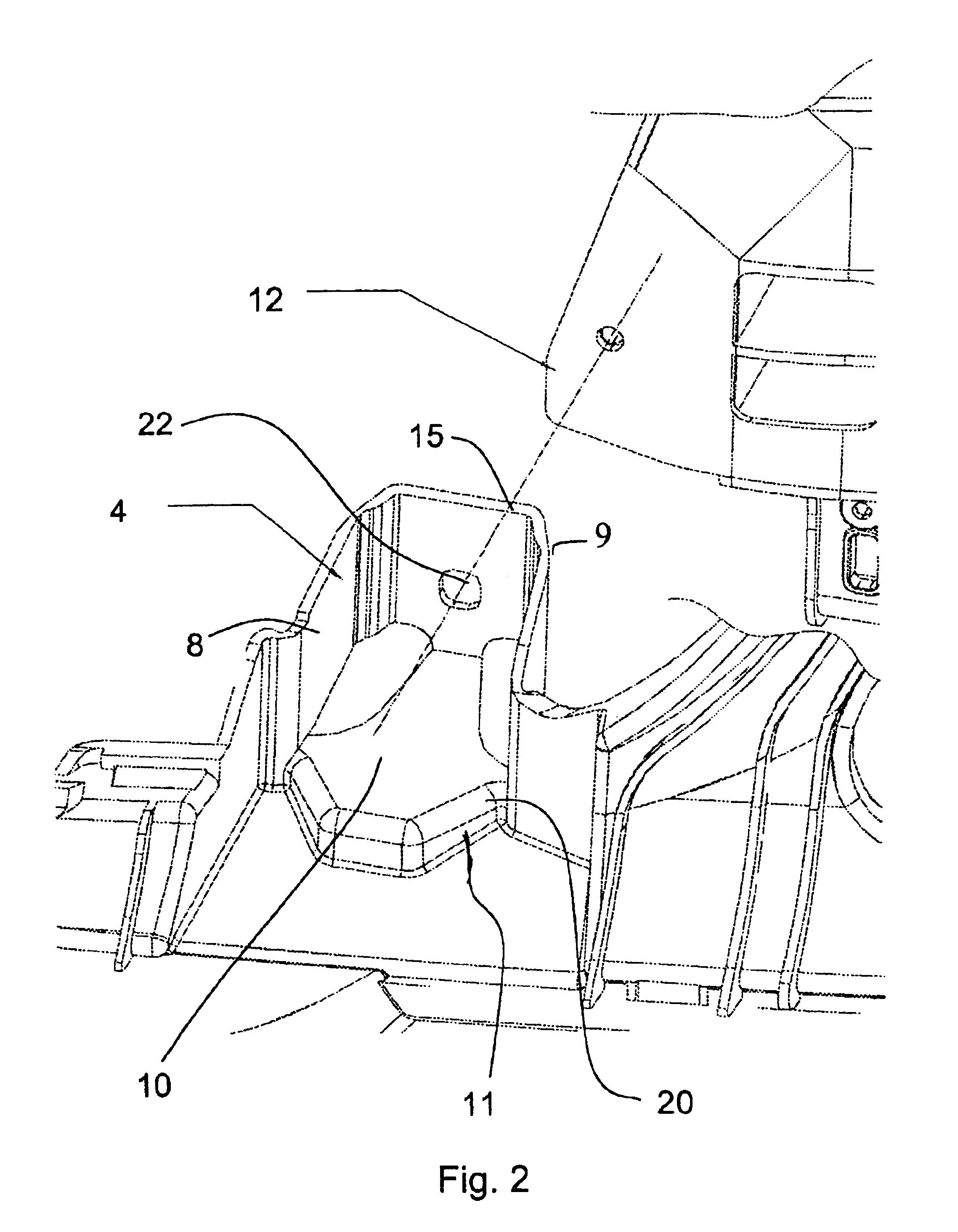
[0039]If the bumper is subjected to a bump or shock impact, impact forces are introduced into the vehicle carrying structure through the attachment parts 4, 5. Therefore, at least the attachment parts 4, 5 are configured as crash absorbing ele...


PUM


Abstract

An attachment element for a bumper includes a partially closed profile with a back panel and on each side lateral tension struts, a bottom plate, or a cover, wherein the attachment element is configured as a part of the bumper and the configuration of the attachment element acts as crash absorbing element which can absorb shock impacts of up to 4 km / h in an elastic range and at shock impacts between 4 km / h and 15 km / h the crash absorbing elements deform thereby preventing damage to the vehicle carrier.

Description

CROSS-REFERENCES TO RELATED APPLICATIONS[0001]This application claims the priority of German Patent Application Serial No. 102 11 233.9, filed Mar. 13, 2002, pursuant to 35 U.S.C. 119(a)-(d).BACKGROUND OF THE INVENTION[0002]The invention relates to a bumper and in particular to the attachment of a bumper at a front end carrying structure or of a vehicle frame for absorbing deformations upon impact so as to prevent damage to the front end beam of the vehicle frame.[0003]From the prior art DE 197 44 274A1, a bumper is known which is configured as an extruded profile attached to a longitudinal beam (front end beam) of the vehicle, where the bumper is mounted to the longitudinal beam. The end portions of the extruded profile of the bumper, which are connected to the longitudinal beam, are configured as crash absorbing elements and can absorb impacts up to 15 km / h in a so-called solid wall test. In such a test, vehicles are driven against a wall at the above-mentioned speed. Although thi...

Claims


Application Information

Patent Timeline
IPC IPC(8): B60R19/26B60R19/24B60R19/34B60R19/36
CPCB60R19/26B60R19/34B60R19/36
Inventor ZIPFEL, RAINER
Owner PEGUFORM
Learn More