Steam distribution ring for spinning machines

a technology of spinning machines and steam blanketing, which is applied in the direction of dough shaping, manufacturing tools, applications, etc., can solve the problems of requiring more down time and requiring replacement of spinnerets, and achieve the effect of effectively touching the spinner

Inactive Publication Date: 2005-08-09
INVISTA NORTH AMERICA S A R L
View PDF15 Cites 14 Cited by
  • Summary
  • Abstract
  • Description
  • Claims
  • Application Information

AI Technical Summary

Benefits of technology

[0010]The present invention solves the problems of the prior art by providing a simple device attached to the spin head to more effectively contact the spinneret face with steam and to provide a concentrated steam atmosphere to the freshly emerging polymer filaments.
[0011]The device of the present invention is particularly advantageous over the prior art in that it does not require the replacement of a spin pack to keep the face of the spinneret free of hardened polymer deposits, but rather provides easy access to the spinneret face so that it can be readily cleaned. Although wiping the face of the spinneret requires down time, replacing the spin pack requires even more down time. Thus, since the spin pack in a spinning system does not have to be replaced when the steam distribution ring of the present invention is used, the present invention improves spinning systems by reducing process down time as compared to commercially available equipment.
[0012]In addition, the apparatus of the present invention does not require substantial modification of existing equipment. Moreover, the steam distribution ring of the present invention is easy and inexpensive to fabricate.

Problems solved by technology

Although wiping the face of the spinneret requires down time, replacing the spin pack requires even more down time.

Method used


Image

  • Steam distribution ring for spinning machines
  • Steam distribution ring for spinning machines
  • Steam distribution ring for spinning machines

Examples


example 1

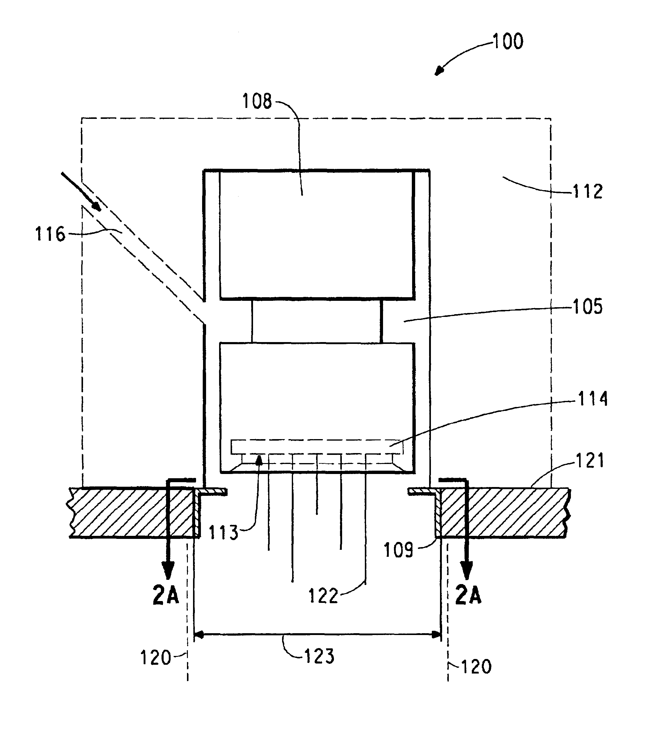
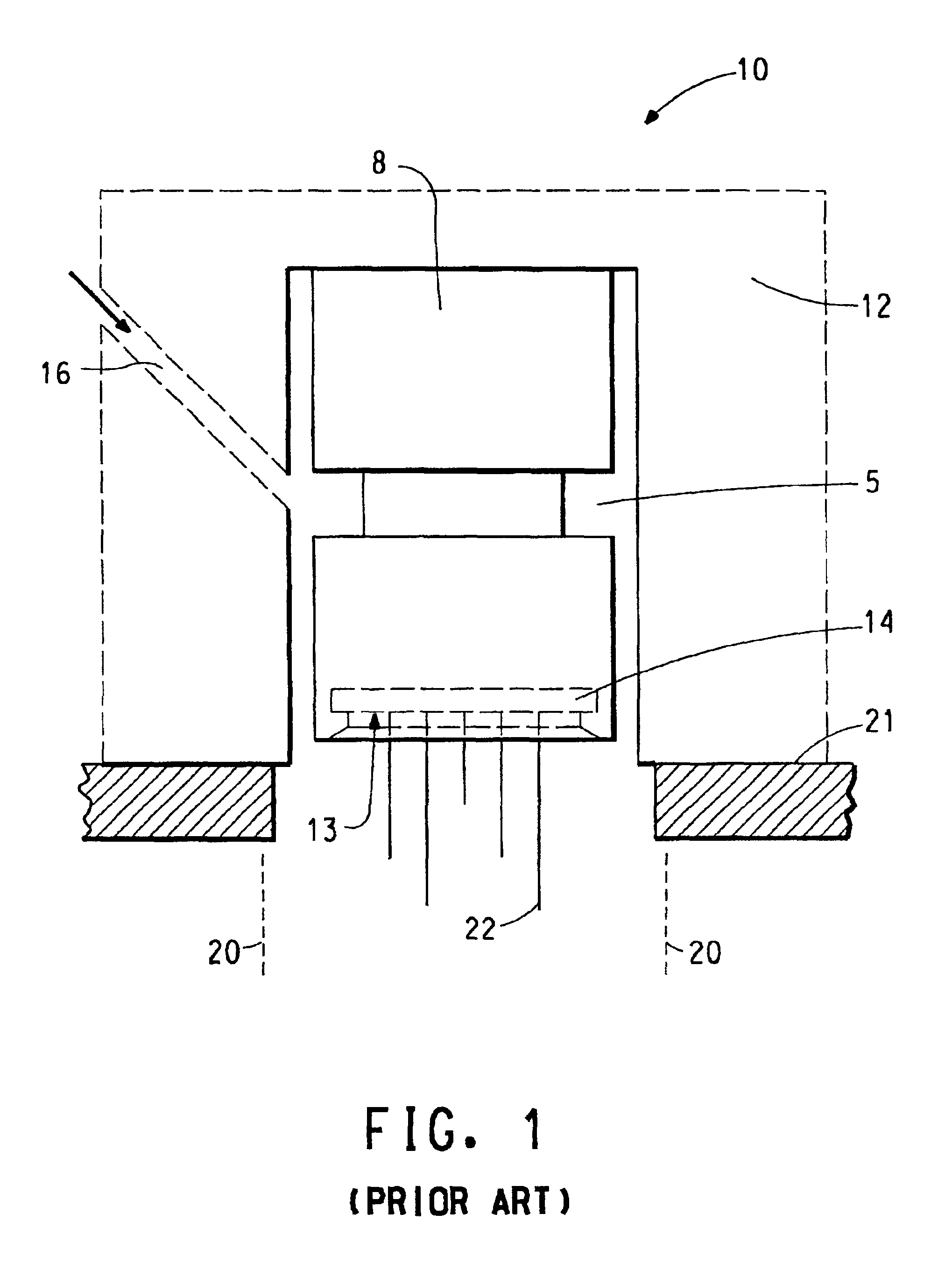
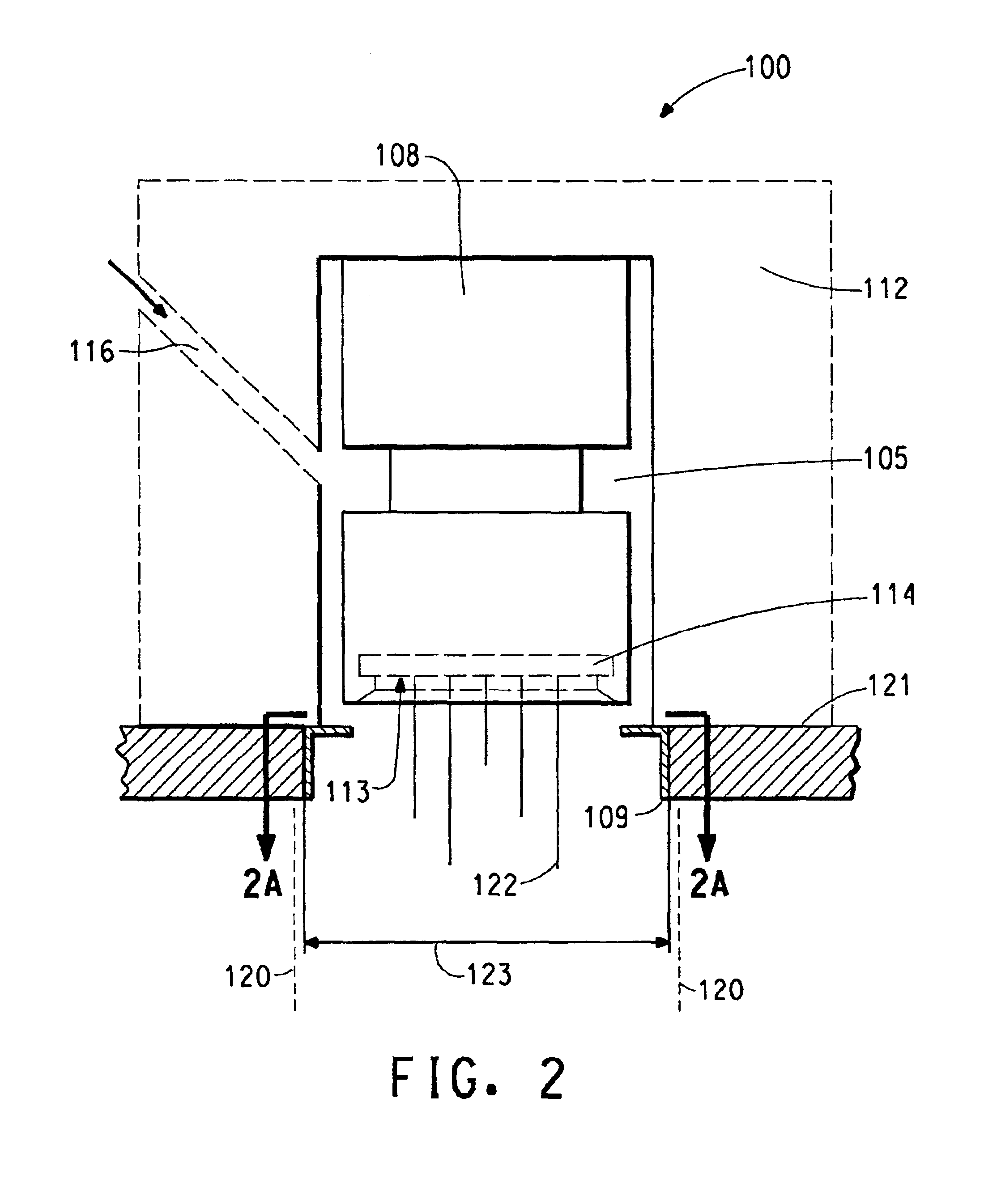
[0047]Example 1 compares a spinning machine which includes a steam blanketing distribution ring according to the embodiment of FIG. 2 of the present invention versus a conventional spinning machine without steam blanketing and with prior art spinneret steam blanketing, provided as shown in FIG. 1 herein. The distribution ring used in this Example had dimensions of 91 mm (outside diameter 109″ in FIG. 2B) and 70 mm for the aperture (diameter 109′″ in FIG. 2B). The polymer in this example was nylon 66 with an initial formic acid relative viscosity of between 53 and 58. The polymer contained titanium dioxide delusterant at a concentration of 0.3% by weight. Forty filaments per yarn were spun at a drawn denier of 34 per yarn, and the overall process draw ratio was 1.25. Yarns were wound up onto a tube core 120 at a surface speed of 6400 meters per minute. The process and apparatus used in this example was similar to that of Example 2 of U.S. Pat. No. 5,750,215 (Steele et al.).

[0048]The ...

example 2

[0051]This Example was performed according to Example 1, and with the steam distribution ring of the present invention. This Example shows that the use of the steam distribution ring of the present invention with spinneret steam blanketing results in an increase in tenacity and elongation in the filaments compared to the use of spinneret steam blanketing without the steam ring. This resulted in an improvement in quality, Q, of the yarn through the use of the steam distribution ring.

[0052]The data obtained in Examples 1 and 2 are compared in three ways shown in FIGS. 5, 6, and 7. First, in FIG. 5, the yarn tenacity is plotted versus the steam flow to the steam blanketing system. In every case where the steam distribution ring was used, and steam was flowing to the steam blanketing system, the yarn tenacity was superior to that of the control. Next, in FIG. 6, the yarn elongation to break is plotted versus the steam flow to the steam blanketing system. In cases where the steam distrib...


PUM

PropertyMeasurementUnit
diameteraaaaaaaaaa
diameteraaaaaaaaaa
steam pressuresaaaaaaaaaa

Abstract

A spinneret steam blanketing system for blanketing the face of a spinneret with gas. The system includes a steam distribution ring surrounding a filament array, where the steam distribution ring abuts the spin head and is removably mounted to said spin head. The steam distribution ring is removed and the face of the spinneret may be wiped clean, without the need for removing and replacing the spin pack.

Description

CROSS REFERENCE TO RELATED APPLICATION[0001]This Application claims priority from and incorporates by reference in its entirety U.S. Provisional Application No. 60 / 213,523 filed Jun. 23, 2000.FIELD OF THE INVENTION[0002]The invention relates to the production of synthetic polymeric filaments and particularly to a spinneret steam blanketing apparatus for blanketing the exposed face of a spinneret with gas which is readily removable from the spin head.DESCRIPTION OF RELATED ART[0003]Most synthetic polymeric filaments, such as polyesters, are melt-spun, i.e., they are extruded from a heated polymeric melt. In current processes, after the freshly extruded molten filamentary streams emerge from the spinneret, they are quenched by a flow of cooling gas to accelerate their hardening. They can then be wound to form a package of continuous filament yarn or otherwise processed, e.g., collected as a bundle of parallel continuous filaments for processing, for example, as a continuous filamentar...

Claims


Application Information

Patent Timeline
Patent Type & Authority Patents(United States)
IPC IPC(8): D01D4/04D01D4/00
CPCD01D4/00D01D4/04
Inventor BRADY, BOBBY R.GOSHORN, ELMER L.OVERTON, FRANK H.STEELE, RONALD E.
Owner INVISTA NORTH AMERICA S A R L
Why Eureka
Try Eureka