
Assay catheter with pressure monitoring

a technology of pressure monitoring and assay catheter, which is applied in the field of catheters, can solve the problems of tissue necrosis, fluid coupled system not user-friendly, and not well suited for the clinical environment, and achieve the effect of minimizing the exten

Inactive Publication Date: 2010-04-29
TWIN STAR MEDICAL
View PDF15 Cites 29 Cited by
  • Summary
  • Abstract
  • Description
  • Claims
  • Application Information

AI Technical Summary

Benefits of technology

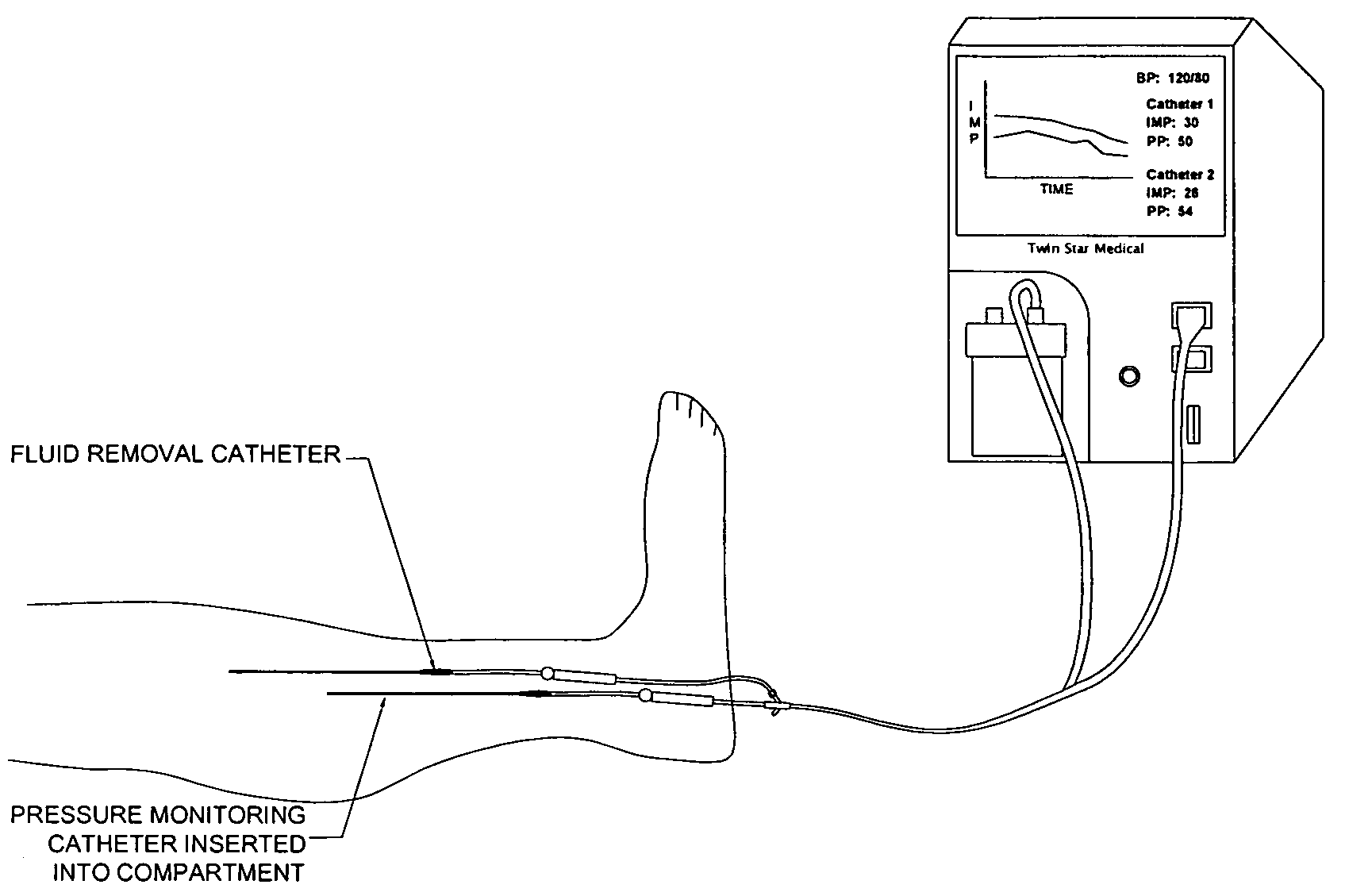
[0016]In a preferred embodiment, the apparatus comprises one or more sensors within a catheter, for use in determining one or more corresponding parameters such as tissue pressure, the catheter being configured and used in a manner that permits the apparatus to be positioned in tissue in a manner that permits the sensor(s) to effectively contact fluid tissue within the site, but that minimizes the extent to which the sensor(s) can be impinged upon by non-fluid tissue itself.
[0018]Alternatively, the apparatus itself is considered novel, and can be used, solely for the purpose of improved sensor placement and use. More preferably, the catheter of this invention provides both improved sensor placement and use, as well as fluid delivery / removal means, and in turn, corresponding options adapted to improve clinical relevance.

Problems solved by technology

High tissue pressures can be indicative of poor tissue perfusion, which can lead to tissue necrosis.
These fluid coupled systems are not user friendly and not well suited for the clinical environment.
Impingement of the tissue on a sensor surface can often provide false or incorrect readings.
This approach has its own drawbacks, however, and does not work for “front looking” fiber optic and other such sensors that do not allow for side port orientations.
Such methods typically do not allow for analyzing the most clinically relevant interstitial fluid, which is found in the manifold tube or other tubing close to and proximal to the manifold tube, since this clinically relevant fluid is the most recently removed fluid from the tissue.

Method used


Image

  • Assay catheter with pressure monitoring
  • Assay catheter with pressure monitoring
  • Assay catheter with pressure monitoring

Examples


Embodiment Construction

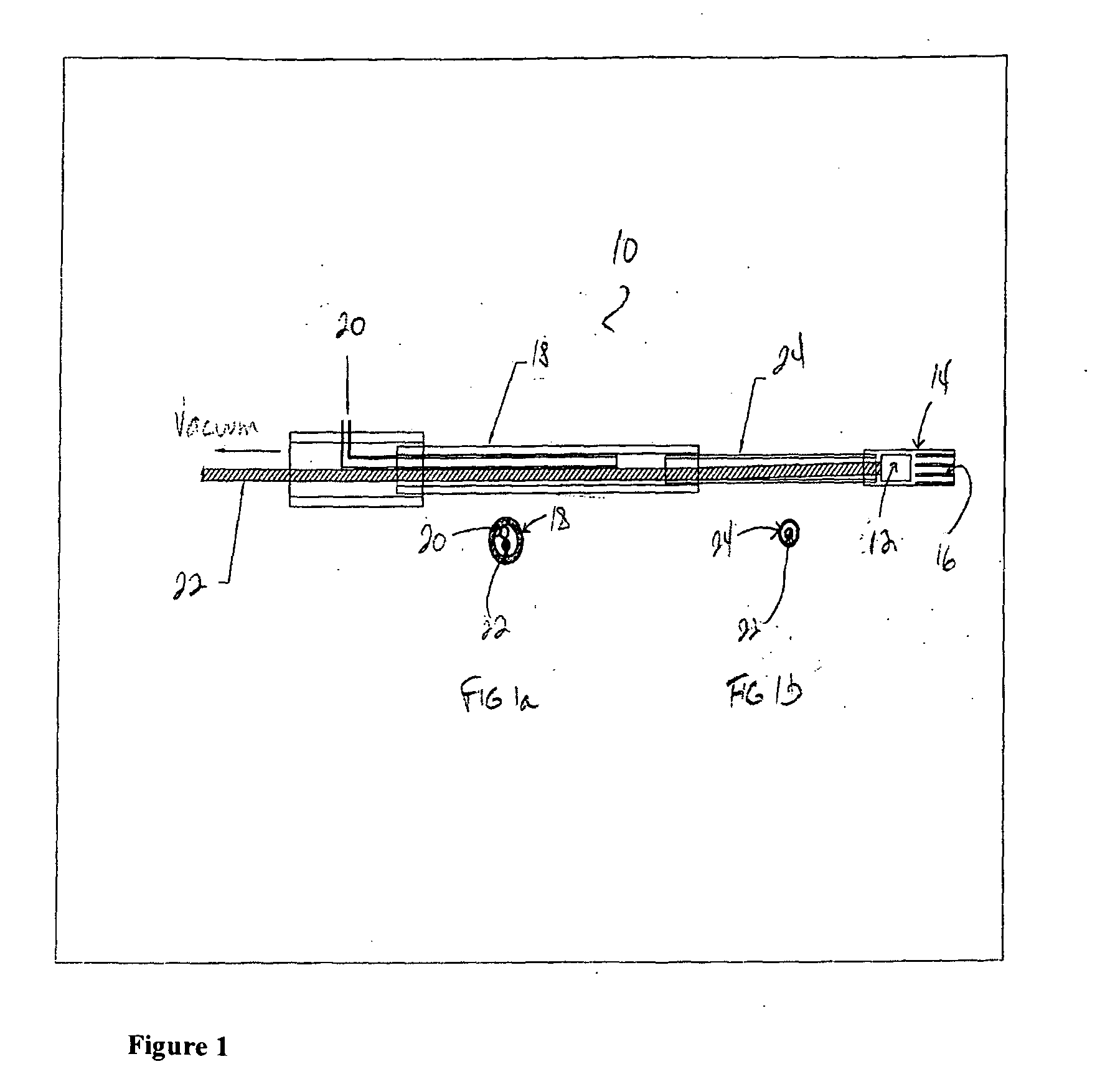
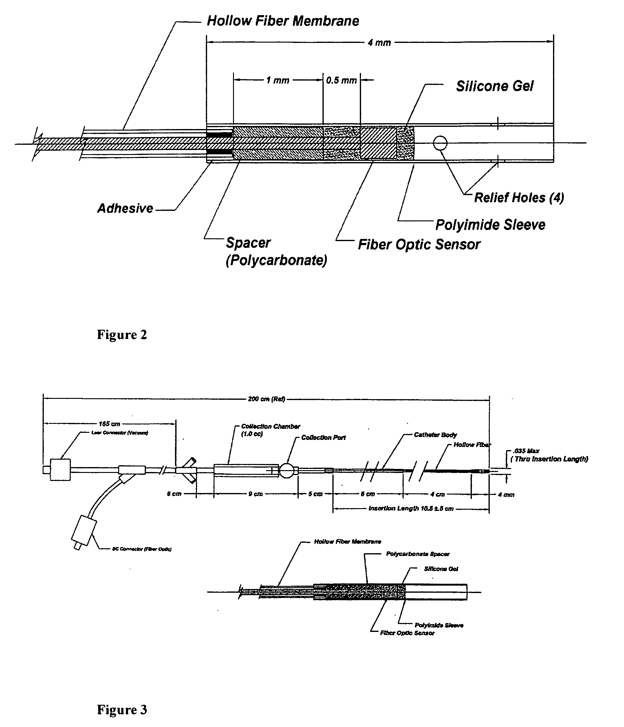
[0019]An apparatus of this invention permits the use of a sensor needing to have direct contact with tissue fluids to be placed within or amidst non-fluid tissue itself, in a manner that substantially prevents non-fluid tissue from impinging upon the sensor surface. In one preferred embodiment, the sensor tip is placed sufficiently back (proximal) from an exposed tip of the apparatus, in order to let fluid, but not non-fluid tissue, access the sensor itself. In turn, in order to avoid the creation of an air bubble or other artifact within the exposed apparatus tip, one or more suitable vents are preferably positioned between the sensor itself and the apparatus tip, thereby permitting what little air or artifact there may be in the apparatus tip to escape as the tip itself is filled with fluid.

[0020]The apparatus comprises one or more sensors that can be positioned within the catheter, and in turn, within the tissue site, in a manner that permits its use without occluding necessary o...


PUM


Abstract

An apparatus adapted to position a functional device tip, such as a sensor, in a body site having both fluid and non-fluid tissue components, in a manner that substantially mitigates the impingement of non-fluid tissue impingement on the device tip. One such apparatus can be used to both remove fluid from a tissue site, such as a site exhibiting tissue swelling, and to determine tissue pressure, using a single catheter. An apparatus can provide a pressure sensor that is adapted to be positioned and used within the tissue site itself, without substantial impingement by non-fluid tissue, and optionally also provides the ability to concurrently remove and / or deliver fluids or components thereof to or from the tissue site.

Description

TECHNICAL FIELD[0001]The present invention relates to the use of catheters for assaying and / or providing fluids within the body. In another aspect, the invention relates to methods and apparatuses for monitoring parameters such as tissue pressure within the body by means of functional tips positioned in the tissue itself.BACKGROUND OF THE INVENTION[0002]In the treatment of several injuries, such as fractures and head injury, it is advantageous to provide pressure monitoring of various tissue parameters, including for instance, tissue pressure. High tissue pressures can be indicative of poor tissue perfusion, which can lead to tissue necrosis. It is also known that the analysis of interstitial fluids can provide diagnostic information, such as tissue micro dialysis, which is a standard of care for traumatic brain injury at some institutions. The removal of fluid can provide therapeutic value in its own right, as described in Applicant's own prior applications and patents.[0003]Typica...

Claims


Application Information

Patent Timeline
Patent Type & Authority Applications(United States)
IPC IPC(8): A61M25/00A61B5/03A61B18/04A61B18/12A61N7/00
CPCA61B5/0084A61B5/021A61B5/036A61B5/053A61B5/145A61M2205/3344A61B5/14546A61B5/1459A61B5/6852A61M2025/0002A61B5/14539
Inventor ODLAND, RICK M.WILSON, SCOTT R.STAEHLE, BRADFORD G.
Owner TWIN STAR MEDICAL
Learn More