

Processing apparatus and cleaning method
a technology of processing apparatus and cleaning method, which is applied in the field of processing, can solve the problems of lowering the yield of products, deteriorating of chamber members, and unlikely deterioration of chamber members, and achieve the effect of efficient cleaning
- Summary
- Abstract
- Description
- Claims
- Application Information
AI Technical Summary
Benefits of technology
Problems solved by technology
Method used
Image

Examples
first embodiment
[0066] In the first embodiment, the end point of the cleaning is calculated by multiplying the period, since the beginning of the cleaning until the decrease in the pressure level, by a predetermined value (e.g. 1.3 in this embodiment). However, any other method for calculating the end point based on the monitored pressure data can be employed, as long as an accurate end point can be obtained. For example, instead of multiplying the above period, the end point may be obtained by adding a predetermined period of time to the time the pressure level begins to be decreased.
[0067] Instead of setting the reference time when the pressure begins to decrease, the end point may be obtained by performing the above multiplication or addition to the reference time when the pressure level indicates the highest level (e.g. eleven minutes as shown in FIG. 3A). Accordingly, a reference time can arbitrarily be set, during the cleaning process, as long as a peculiar pressure variation can be observed ...
second embodiment
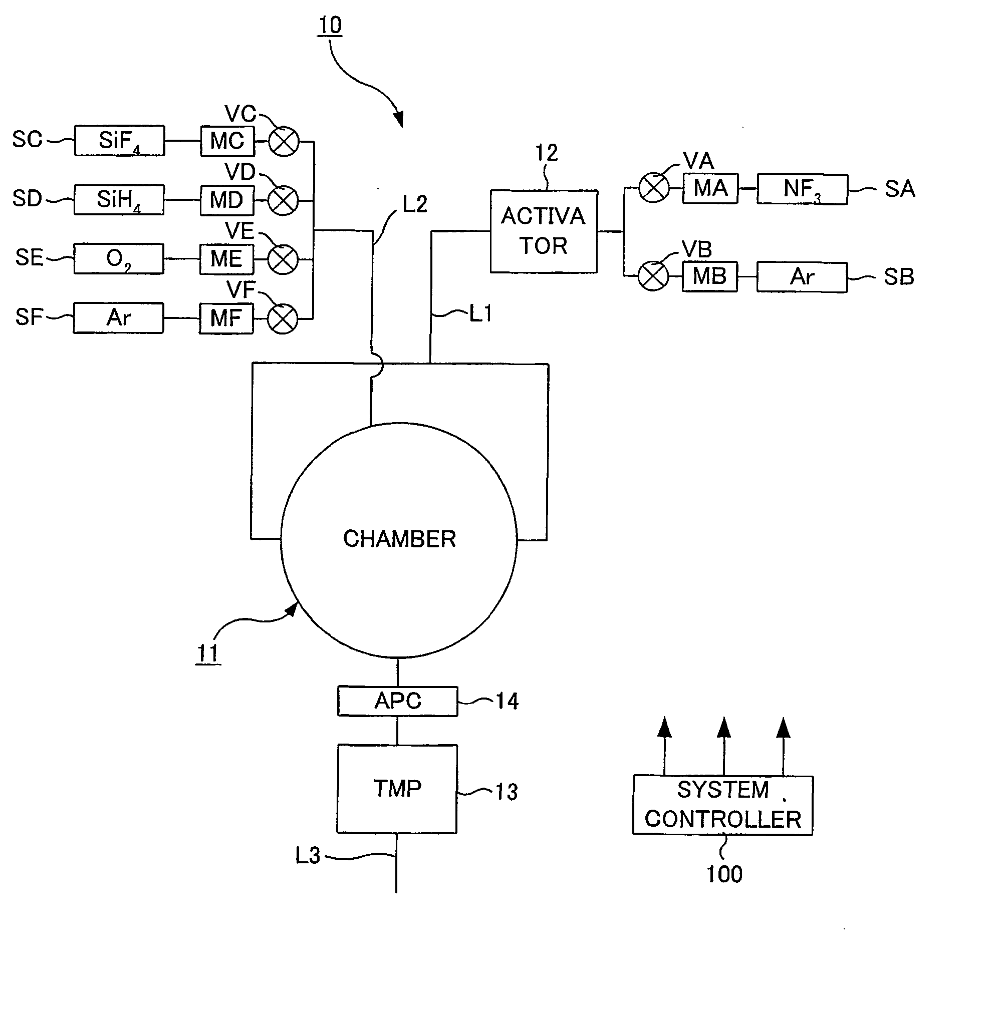
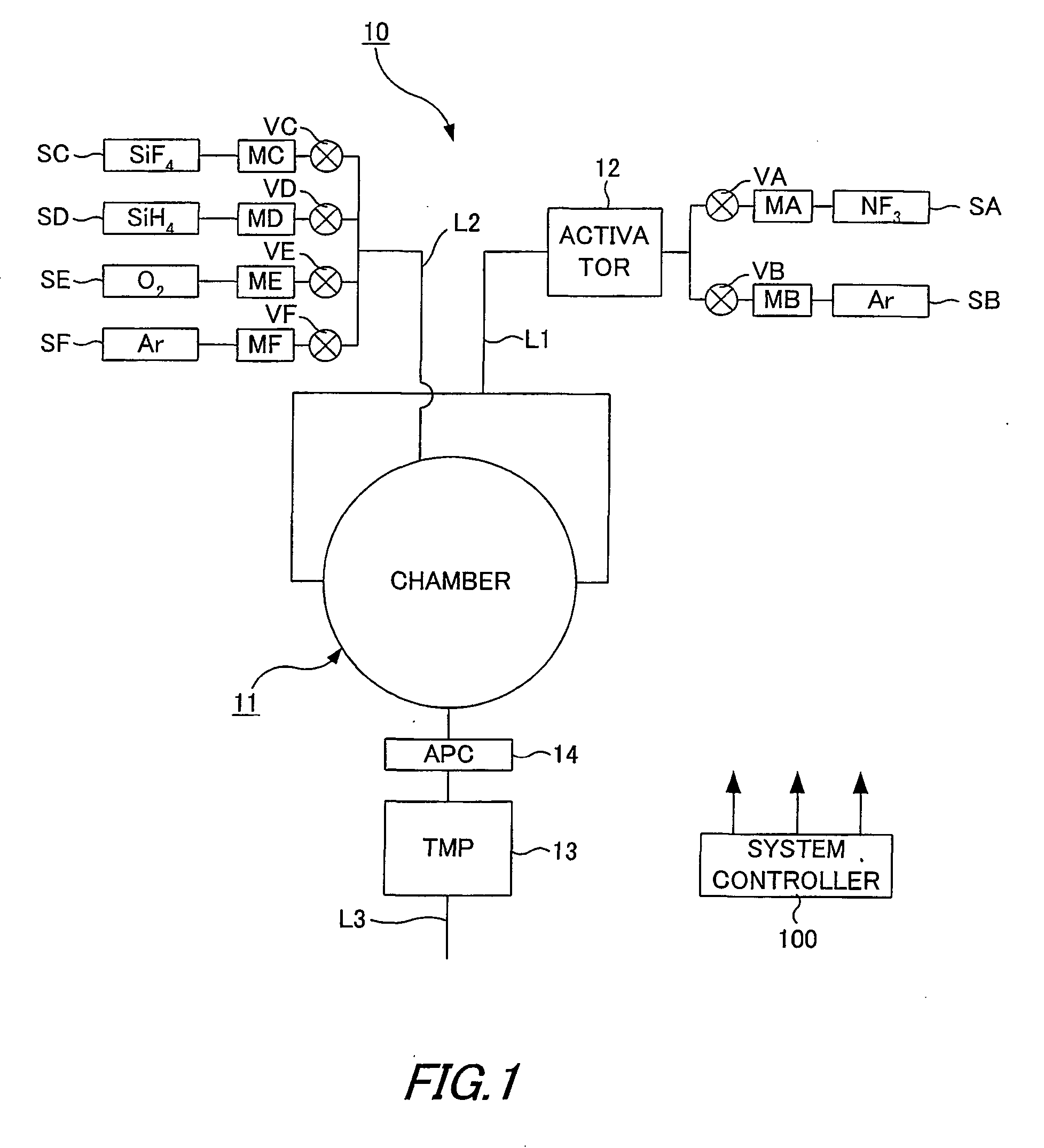
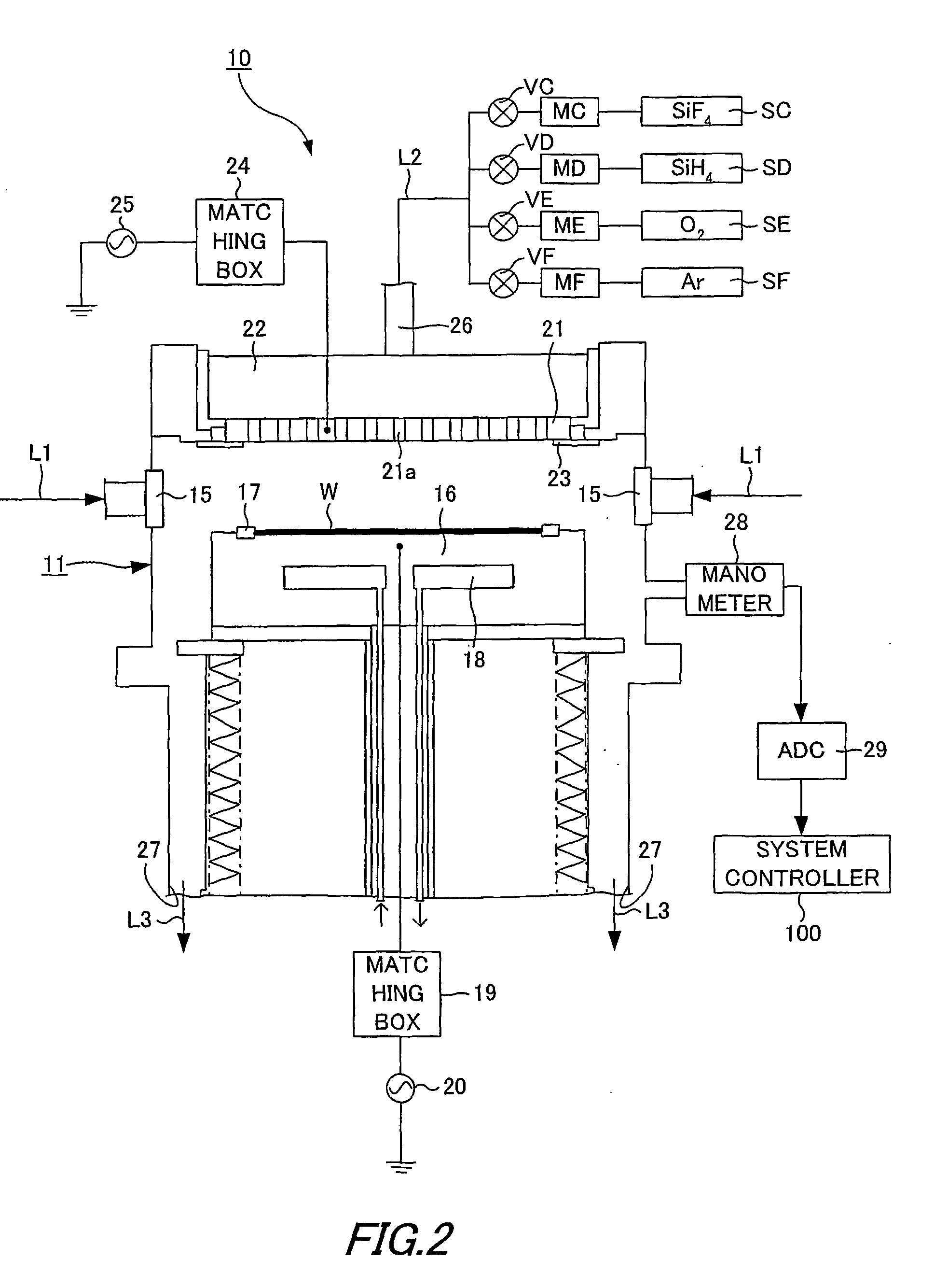
[0069] FIG. 4 shows the structure of a processing apparatus 10 according to the second embodiment of the present invention. In FIG. 4, the same components are identified by the same reference numerals as those of FIGS. 1 and 2. Likewise the first embodiment, the processing apparatus 10 according to the second embodiment first forms a SiOF film on the wafer W inside the chamber 11, and then performs cleaning the inside of the chamber 11 using NF.sub.3. As shown in FIG. 4, the processing apparatus 10 of the second embodiment has substantially the same structure as that of the first embodiment. However, the processing apparatus 10 of this embodiment does not include the manometer 28, and does not detect the end point of cleaning based on the pressure data. Instead, the processing apparatus of this embodiment includes an oxygen densimeter for measuring the density of oxygen, and detects the end point based on the density of oxygen during the cleaning.
[0070] As illustrated in FIG. 4, the...
third embodiment
[0086] FIG. 6 shows the structure of a processing apparatus 10 according to the third embodiment of the present invention. In FIG. 6, the same components are identified by the same reference numerals as those of FIG. 2. Likewise the first embodiment, the processing apparatus 10 according to the third embodiment forms a SiOF film on the wafer W inside the chamber 11, and cleans the inside of the chamber 11 using NF.sub.3.
[0087] As shown in FIG. 6, the processing apparatus 10 of this embodiment has substantially the same structure as that of the processing apparatus of the first embodiment. However, in the processing apparatus 10 of the third embodiment, the chamber 11 does not include the manometer 28, and the system controller 100 does not determine the end point of cleaning based on pressure data obtained by the manometer 28. Instead, in the processing apparatus 10 of this embodiment, plasma are generated inside the chamber 11, and the end point of cleaning is calculated based on d...
PUM
| Property | Measurement | Unit |
|---|---|---|
| Thickness | aaaaa | aaaaa |
| Pressure | aaaaa | aaaaa |
| Electrical resistance | aaaaa | aaaaa |
Abstract
Description
Claims
Application Information