
Aerobic ramp

a step system and aerobic technology, applied in the field of aerobic steps, can solve the problems of participants perspiration, large load placed on the knee joint, and substantial compression load on the knee joint, and achieve the effect of reducing stress on the knee joint and facilitating the degree of intensity of workou

Inactive Publication Date: 2005-08-09
GT MERCHANDISING & LICENSING +1
View PDF56 Cites 41 Cited by
  • Summary
  • Abstract
  • Description
  • Claims
  • Application Information

AI Technical Summary

Benefits of technology

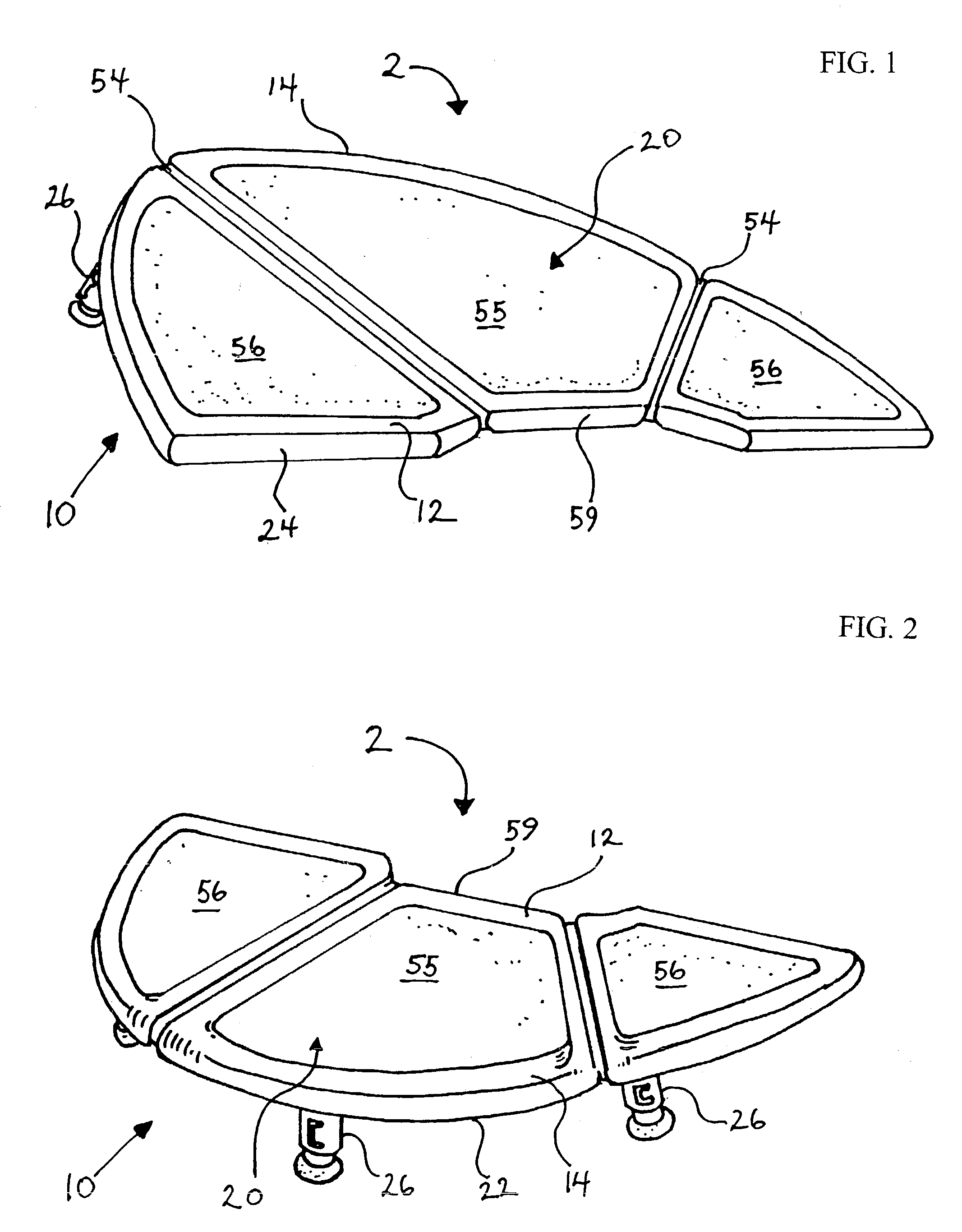
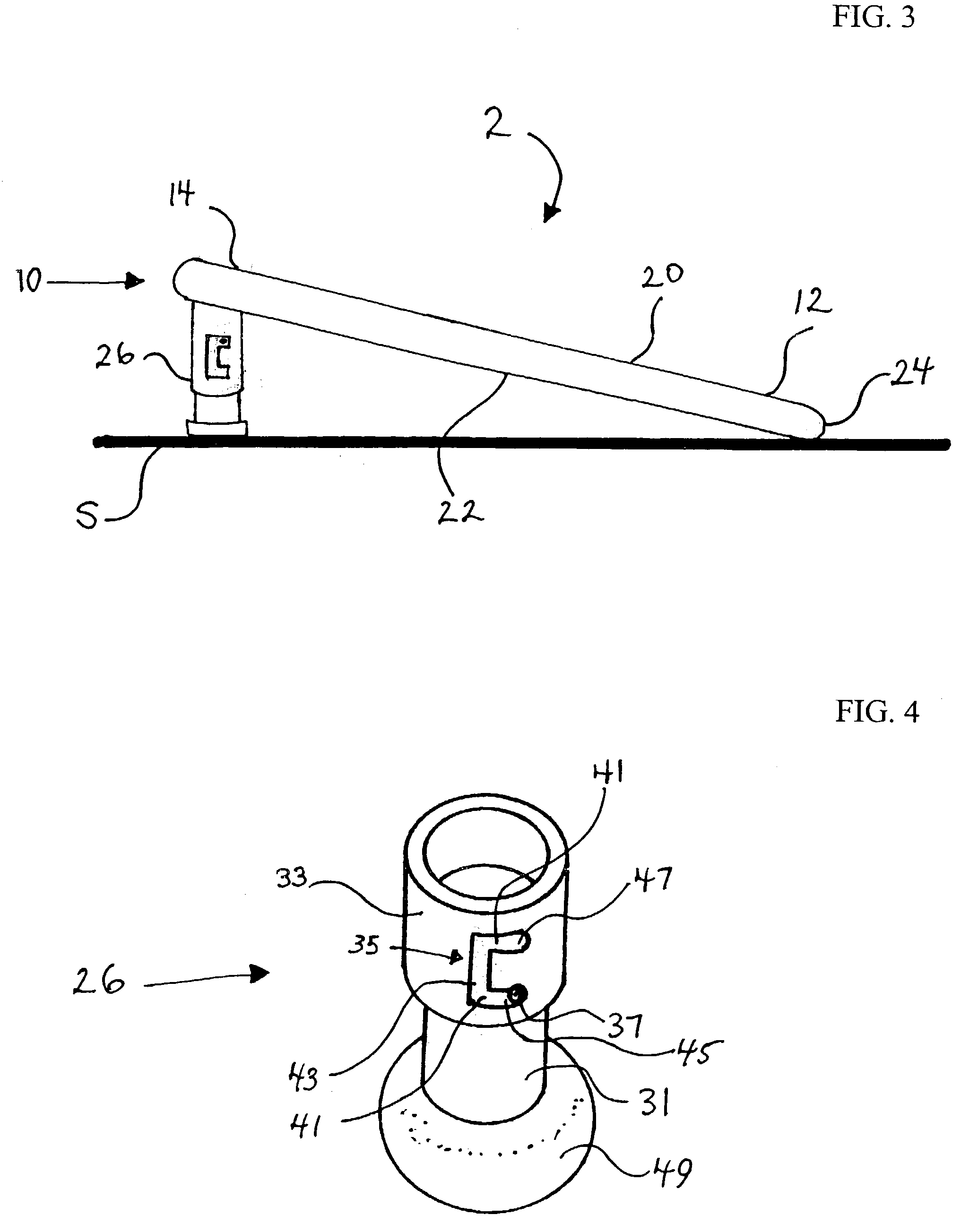
[0006]The foregoing problems are solved and an advance in the art is obtained by a novel step exercising system for an aerobic step workout comprising a portable inclined step ramp. The ramp is sloped towards a user such that the user can step onto the ramp at various height levels, thereby easily regulating the degree of intensity of the workout. There is no need to suspend the workout to perform a height adjustment, as is the case when using a level aerobic step platform. There is also reduced stress on the knee joint.

Problems solved by technology

Another drawback of existing level step platforms is the great amount of load placed on the knee joint while performing the step up to the level platform.
This places the knee joint under a substantial compression load.
Further, most aerobic or cardiovascular activity such as stepping will cause the participants to perspire.
This perspiration has a tendency to pool on the level step platform, creating the potential for injury by slipping on the surface.

Method used


Image

  • Aerobic ramp
  • Aerobic ramp
  • Aerobic ramp

Examples


second embodiment

[0035]Turning now to FIGS. 5 and 6, the ramp 10 is shown wherein the underside 22 mounts adjustable legs 52 proximate to the front portion 12 of the ramp 10. The adjustable legs 52 directly contact the support surface S and enable the leading edge 24 to be positioned above the support surface rather than resting directly thereon. This allows a user to intensify the workout by having a higher initial starting point for the workout.

[0036]As can be seen in any of FIGS. 1–2 and 5, and as further illustrated in FIG. 7, the upper workout surface portion 20 of the ramp 10 comprises grooves 54 that divide the surface into visually distinct workout areas. The grooves 54 can be formed in a variety of ways. If the ramp 10 is formed as a single unit, the grooves 54 can be formed therein during the fabrication process or thereafter in subsequent processing. Alternatively, the grooves 54 could be defined by fabricating the ramp 10 as separate sections that are suitably fastened together such that...

third embodiment

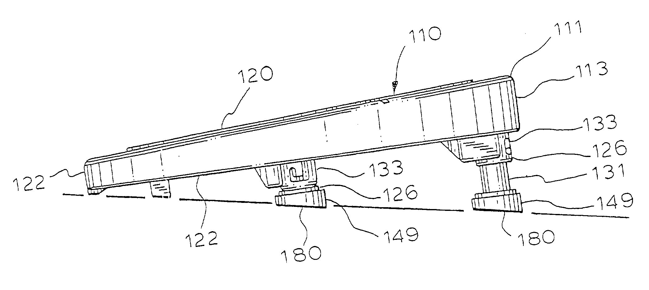
[0040]Referring to FIGS. 8–19, the portable inclined aerobic step ramp 110 of the present invention includes a plurality of adjustable legs 126 affixed to an underside portion 122 and are preferably disposed adjacent to a peripheral edge 113 of the underside portion 122.

[0041]The underside portion 122 is preferably substantially parallel to an upper workout surface portion 120 of a main body 111 of the portable inclined aerobic step ramp 110; and is spaced a distance from the upper workout surface portion 120. The portable aerobic step ramp 110 may be formed in a hollow configuration such that a gap 115 exists between an interior surface 117 of the upper workout surface portion 20 and an interior surface 119 of the underside portion 122 (see FIGS. 15 and 16).

[0042]The adjustable legs 126 preferably include a fixed, outer tubular member 133 and an inner tubular member 131 which is telescopically, slideably received within the outer tubular member 133. An attachment flange 150 is inte...


PUM


Abstract

A step exercising system for an aerobic step workout is constructed as a portable inclined step ramp. The ramp is sloped towards a user such that the user can step up onto the ramp at various heights, thereby regulating the degree of intensity of the workout without having to suspend the workout to adjust the step height, as is the case when using a conventional aerobic step having a raised level platform.

Description

RELATED APPLICATIONS[0001]This application is a Continuation-In-Part of U.S. patent application Ser. No. 10 / 166,573, filed Jun. 10, 2002.BACKGROUND OF THE INVENTION[0002]1. Field of the Invention[0003]This invention relates to step systems for aerobic and cardio-vascular activities.[0004]2. Description of the Prior Art[0005]By way of background, a popular form of cardio-vascular training is aerobic stepping. An aerobic step workout is performed by stepping on and off a raised, level step platform. The steps are choreographed, usually performed to music, and leader-driven by an instructor in a class setting or on videotape for home exercise. Workout intensity is largely dependent on the step platform height. Presently, step platforms require a user to suspend the workout while an adjustment to height is made. This is disruptive. Additionally, a user who is becoming fatigued and who should probably lower the step height will not do so, and instead will continue the workout, allowing f...

Claims


Application Information

Patent Timeline
IPC IPC(8): A63B23/04
CPCA63B23/0458A63B2225/093
Inventor GVOICH, NED
Owner GT MERCHANDISING & LICENSING
Learn More