Blind spot detector system

a detector system and blind spot technology, applied in the direction of pedestrian/occupant safety arrangement, instruments, transportation items, etc., can solve the problems of preventing the problem of adequately resolving the problem of mirrors, difficulty in detecting other vehicles or objects in the blind spot of the vehicle operator, and numerous accidents

Inactive Publication Date: 2005-08-09
ANDERSON DARRYLL
View PDF18 Cites 39 Cited by
  • Summary
  • Abstract
  • Description
  • Claims
  • Application Information

AI Technical Summary

Benefits of technology

[0024]Still another object of the invention is to provide a blind spot detector system which can be removably attached to vehicles and other objects.
[0025]It is an object of the invention to provide improved elements and arrangements thereof for the purposes described which is inexpensive, dependable and fully effective in accomplishing its intended purposes.

Problems solved by technology

A common problem to the operators of motor vehicles is the difficulty in detecting other vehicles or objects in the “blind spots” of the vehicle's operator.
Both of these blind spots are the source of numerous accidents when the driver makes a left or right turn or a left or right lane change.
Vehicle manufacturers have sought to overcome these blind spots through the use of left and right side-view mirrors, however, several limitations have prevented mirrors from adequately resolving the problem.
First, the mirrors do not necessarily reflect the true position of the object in the mirror.
Mirror manufacturers have attempted to give the driver a wider angle of view at the price of having a smaller reflection, giving the operator a false sense of distance.
Second, nighttime use and adverse weather conditions limit the effectiveness of externally mounted mirrors.
Third, a vehicle may have several alternate drivers, each requiring different physical positions of the mirror.
However, a driver may neglect to adjust the mirror after taking control of the vehicle thus forsaking any benefit the mirror may provide.
A limitation common to all the above inventions is the lack of a means to determine and indicate to the user a lack of system integrity.
A malfunction of a blind spot detection device resulting in the failure to detect an object in the vehicle's blind spot may have serious consequences to the vehicle and to its operator.

Method used


Image

  • Blind spot detector system
  • Blind spot detector system
  • Blind spot detector system

Examples


Embodiment Construction

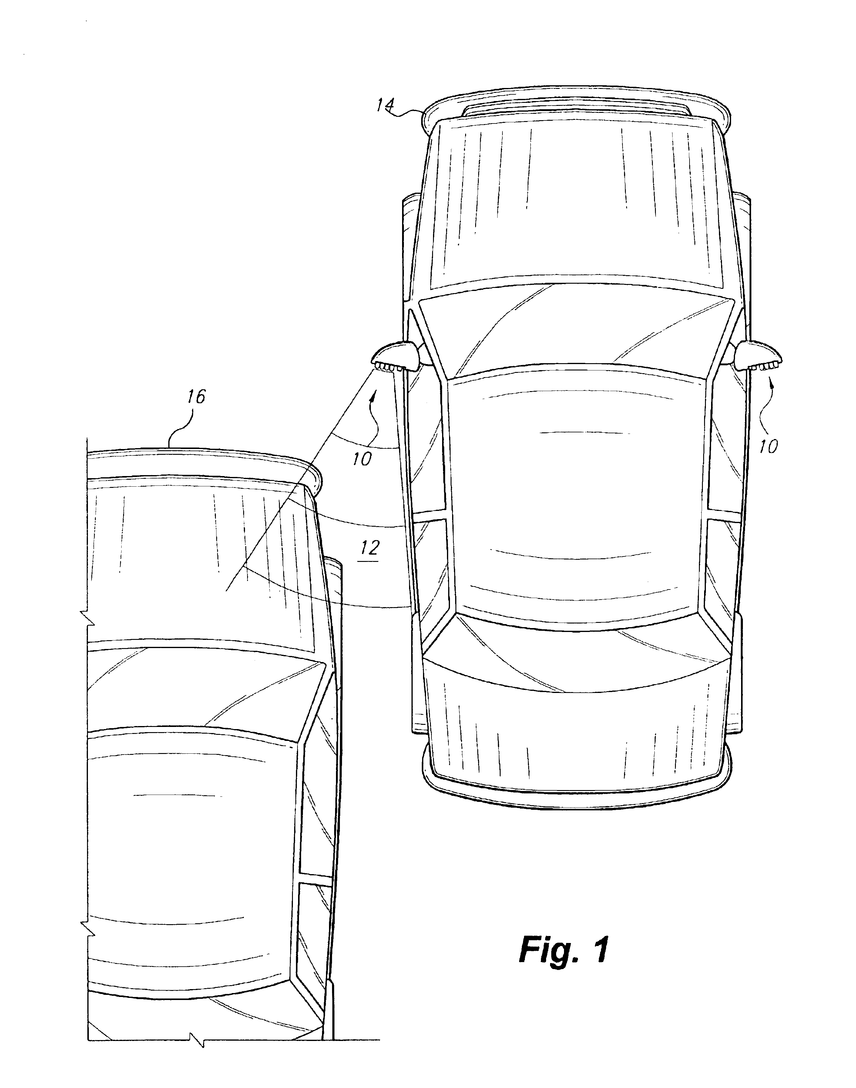
[0039]As shown in FIG. 1, a blind spot detector system 10, mounted on the exterior of a vehicle 14, utilizes light emitting diodes (LEDs) to reflect infrared light from an object 16 in the vehicle's blind spot 12. The reflected light is then detected and a visual indication is presented to the operator of the vehicle 14. The LEDs and infrared detector are frequency modulated at approximately 40 Khz to screen out unwanted light energy.

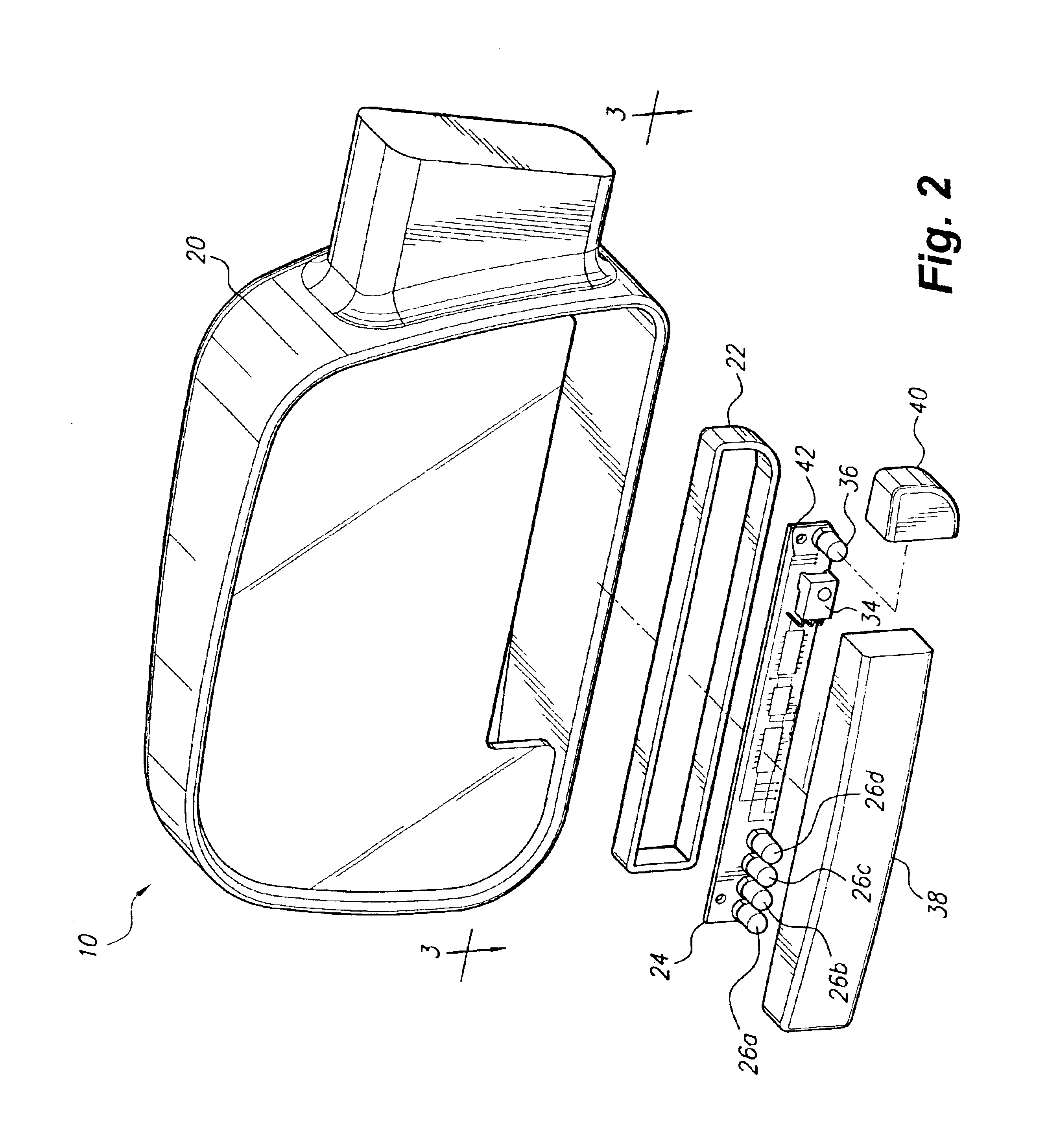
[0040]As shown in FIGS. 2 and 3, the detector system 10 comprises a side view mirror 20 adapted to receive a housing 22 containing circuitry 42 disposed on a circuit board 24. Mounted on the circuit board is at least one infrared LED, 26a-d, an infrared photo detector and demodulator 34, and a bi-color indicator LED 36 that illuminates green when the detector system 10 is active and operational, solid red when the detector system 10 is out of calibration, and flashes red when the detector system 10 has sensed an object 16 within the vehicle's blind spot...


PUM


Abstract

A blind spot detector system adapted to the exterior of a vehicle comprising at least one infrared light emitting diode (LED), an infrared photodetector and demodulator, and a microcontroller. The output power of the infrared transmitter is linearly modulated, enabling the blind spot detector to determine the proximity of the detected object. Furthermore, the transmitter output is frequency modulated to screen out random infrared radiation that might adversely affect the operation of the infrared photodetector. The system is calibrated to the position of the attached vehicle by linearly increasing the output power of the transmitter until the rear quadrant of the vehicle is detected when the transmitter is outputting power at a pre-determined calibration level. During normal operation, an object detected while the transmitted power is greater than a predetermined lower threshold and less than the calibration level will activate a LED indicator on the system housing.

Description

BACKGROUND OF THE INVENTION[0001]1. Field of the Invention[0002]The present invention relates to vehicle safety devices, and more specifically, relates to a system for detecting objects in a vehicle's “blind spot”.[0003]2. Description of the Related Art[0004]A common problem to the operators of motor vehicles is the difficulty in detecting other vehicles or objects in the “blind spots” of the vehicle's operator. A common blind spot is to the rear left of the operator's seat, and a right-side blind spot extends outward from the rear right quadrant of the vehicle. Both of these blind spots are the source of numerous accidents when the driver makes a left or right turn or a left or right lane change.[0005]Vehicle manufacturers have sought to overcome these blind spots through the use of left and right side-view mirrors, however, several limitations have prevented mirrors from adequately resolving the problem. First, the mirrors do not necessarily reflect the true position of the object...

Claims


Application Information

Patent Timeline
Patent Type & Authority Patents(United States)
IPC IPC(8): B60Q1/50B60Q1/52B60R1/12B60Q1/26G01S17/93G01S17/00G01S13/93G01S13/00G01S17/931
CPCB60Q1/2665B60Q9/008B60R1/12G01S17/936B60R1/1207B60R2001/1215B60R2001/1223G01S2013/9332G08G1/167G01S2013/9315G01S17/931
Inventor ANDERSON, DARRYLLCERNASOV, ANDREI
Owner ANDERSON DARRYLL
Why Eureka
Try Eureka