Buffered oversampling analog-to-digital converter with improved DC offset performance
- Summary
- Abstract
- Description
- Claims
- Application Information
AI Technical Summary
Benefits of technology
Problems solved by technology
Method used
Image
Examples
Embodiment Construction
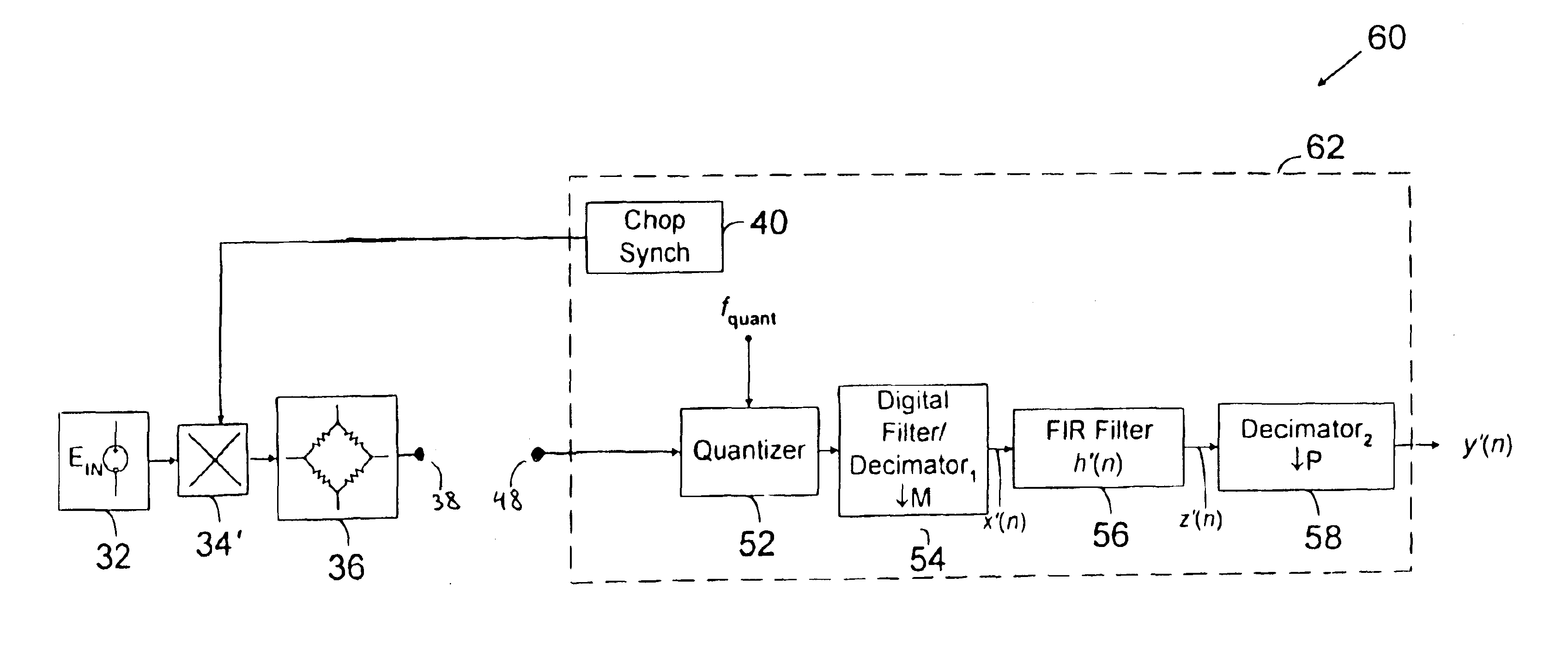
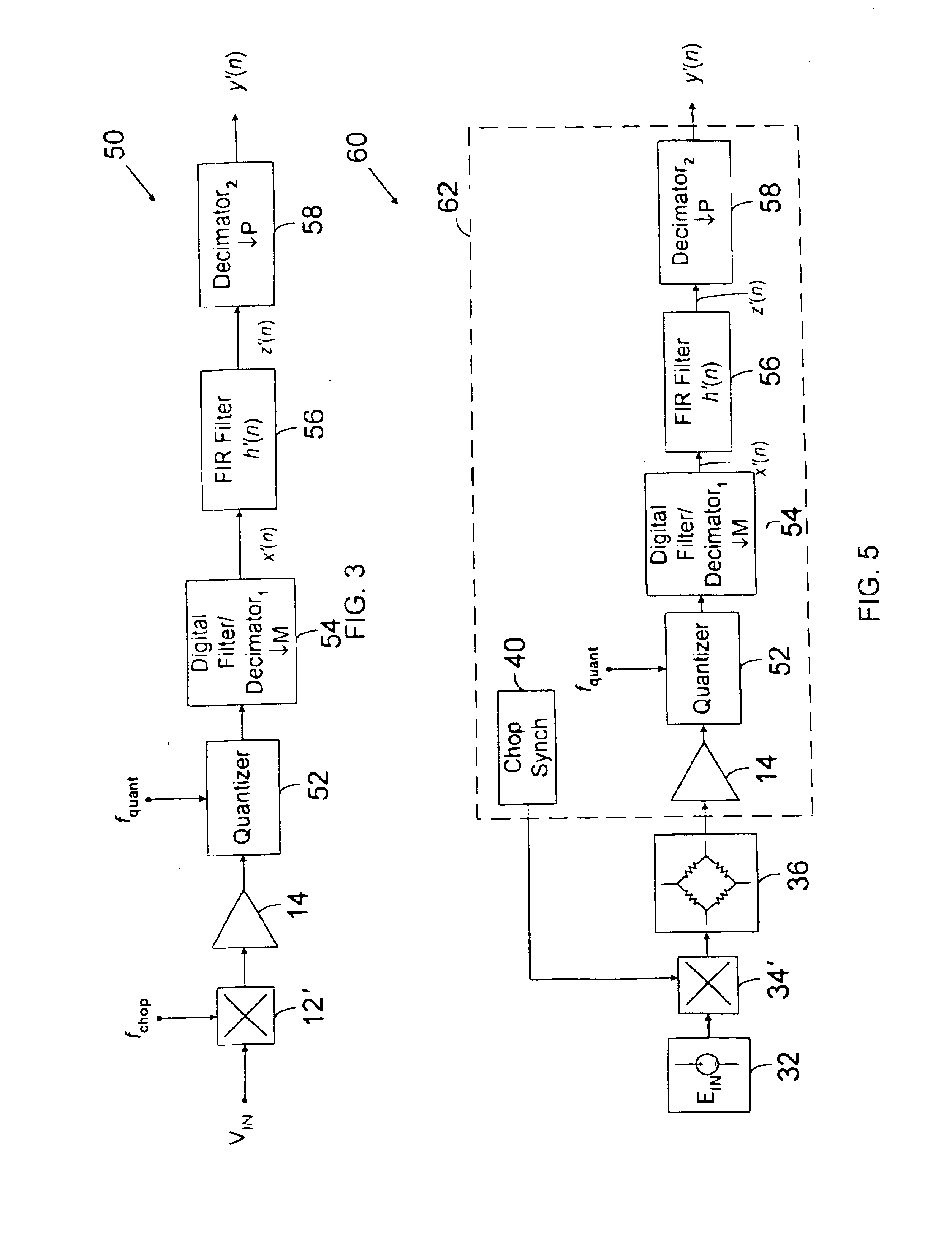
[0028]Referring to FIG. 3, an A / D converter is described. A / D converter 50 includes analog is chopper 12′, buffer amplifier 14, quantizer 52, digital filter and decimator154, FIR filter 56 and decimator258.
[0029]Analog chopper 12′ chops analog input signal VIN with a square wave of frequency fchop, which successively reverses the polarity of VIN. Analog chopper 12′ may be implemented using any well-known analog chopping circuitry. For example, as shown in FIG. 4, if input signal VIN is a differential signal VIN=(VIN+−VIN−), analog chopper 12′ may be implemented using cross-coupled switches 24, 25, 26, and 27. Switch 26 is controlled by complementary chop signal {overscore (Q)}, and is coupled between VIN+ and VCOUNT−. Switch 27 is controlled by complementary chop signal {overscore (Q)}, and is coupled between VIN− and VCOUT+. Chop signals Q and {overscore (Q)} are complementary logic signals of frequency fchop. For example, when Q is HIGH and {overscore (Q)} is LOW, VCOUT+=VIN−, and...
PUM
 Abstract
Description
Claims
Application Information
 - R&D
- Intellectual Property
- Life Sciences
- Materials
- Tech Scout
- Unparalleled Data Quality
- Higher Quality Content
- 60% Fewer Hallucinations
Browse by: Latest US Patents, China's latest patents, Technical Efficacy Thesaurus, Application Domain, Technology Topic, Popular Technical Reports.
© 2025 PatSnap. All rights reserved.Legal|Privacy policy|Modern Slavery Act Transparency Statement|Sitemap|About US| Contact US: help@patsnap.com


