Optical devices employing beam folding with polarizing splitters

a technology of optical beams and splitters, applied in the field of optical systems, can solve the problems of large size restrictions in the processing of optical beams, large space occupation of beam folders implemented with conventional reflectors, and large space occupation of beam folders, etc., and achieve the effect of increasing optical length and facilitating beam manipulation

Inactive Publication Date: 2005-08-09
HONEYWELL INT INC
View PDF14 Cites 2 Cited by
  • Summary
  • Abstract
  • Description
  • Claims
  • Application Information

AI Technical Summary

Benefits of technology

[0006]The present invention offers optical devices for increased optical length in restricted volumes using polarizing beam splitters reflectors that repolarize or convert the polarization of an incident beam, thus providing greater optical manipulation of the beam in a given physical space. Some of the devices employ polarized beams, others operate with non-polarized beams.

Problems solved by technology

Many devices for processing optical beams have significant size restrictions, yet require relatively long lengths for the beams inside the devices.
Beam folders implemented with conventional reflectors generally do not save large amounts of space.
However, beam splitters typically suffer from low optical efficiency.
In adsdition, such devices do not perform other optical functions within the device.

Method used


Image

  • Optical devices employing beam folding with polarizing splitters
  • Optical devices employing beam folding with polarizing splitters
  • Optical devices employing beam folding with polarizing splitters

Examples


Embodiment Construction

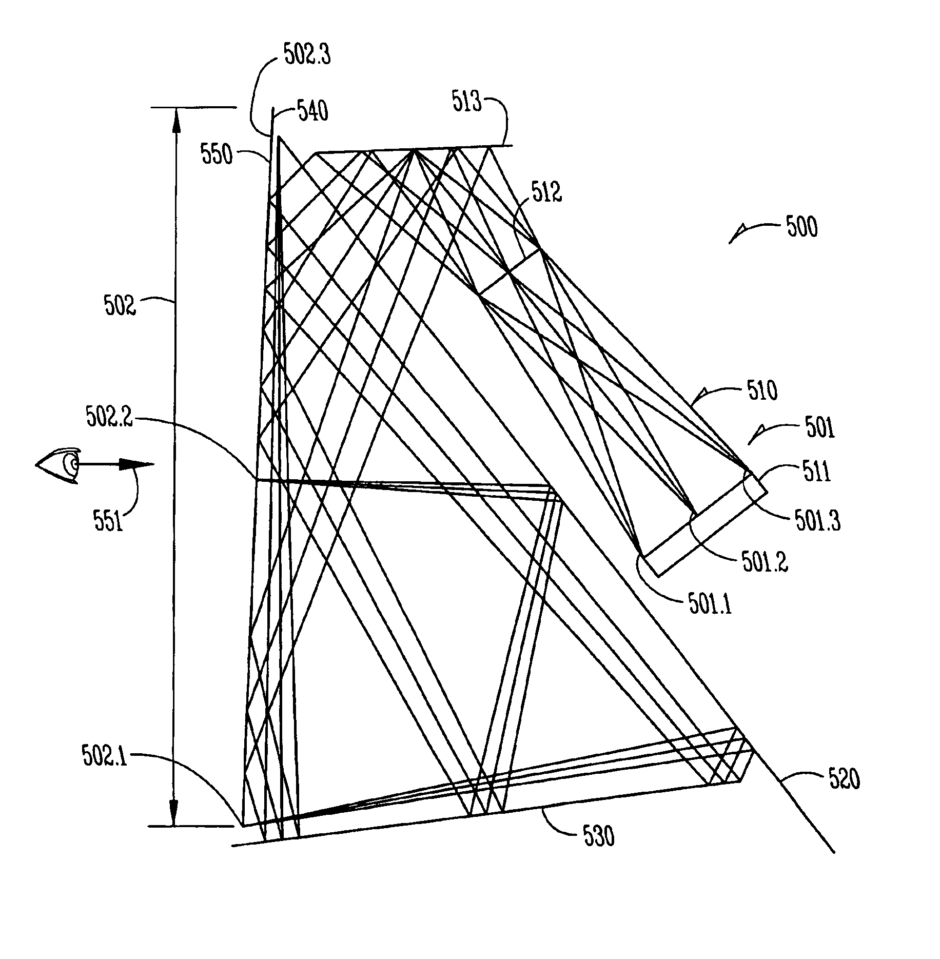
[0022]FIG. 2 shows schematically an optical device 200 for folding an incident beam 201 to produce an exit beam having a beam length greater than an associated dimension 203 of the device. Light 201 from any type of source 210 has a polarization indicated at 204. The source could be inherently polarized, or a conventional analyzer (not shown) could be placed in the path of incident beam 201 into or within device 200, even at the exit. The polarization mode is arbitrary; it could be linear vertical or horizontal, circular right- or left-handed, etc. A polarizing beam splitter 220 is positioned so that its rejection axis lies along the polarization mode of beam 201. Therefore, the beam is reflected from splitter 220. The reflected beam then passes through polarizing bean splitter 240, whose rejection axis is perpendicular to that of splitter 220, and encounters a reflecting repolarizer 230. The beam, now having a different or opposite polarization, as symbolized at 205, next encounter...


PUM


Abstract

A beam folder increases optical length with polarizing beam splitters and reflectors that repolarize a beam by retarding it. An incident beam encounters the beam splitters multiple times, and are both passed and rejected by the same splitters. The splitters and repolarizing reflectors can be shaped to perform optical functions in a smaller volume. Valves and controls can varyl the beam intensity and combine multiple beams. Applications include projection, imaging, collimating, mixing, and balancing.

Description

[0001]This application is a continuation of U.S. application Ser. No. 09 / 751,339 filed on Dec. 29, 2000 now U.S. Pat. No. 6,597,504 which is incorporated herein by reference.TECHNICAL FIELD[0002]The present invention relates to optical systems, and more particularly concerns devices for folding an optical beam so as to increase its beam length.BACKGROUND[0003]Many devices for processing optical beams have significant size restrictions, yet require relatively long lengths for the beams inside the devices.[0004]A common technique for increasing the length of a beam within an optical device is to fold the beam inside the device. Binoculars, for example, commonly reflect incident optical beams in a “Z” shape to increase their optical length while keeping their physical length small. Many reflex cameras employ a pentaprism to increase the optical length of their viewfinders within a small camera body. Projection systems of various kinds attain wider deflection angles in a shorter distanc...

Claims


Application Information

Patent Timeline
Patent Type & Authority Patents(United States)
IPC IPC(8): G02B27/28G03B21/10G02B5/04
CPCG02B27/283Y10S359/90
Inventor DUBIN, MATTHEWLARSON, BRENT
Owner HONEYWELL INT INC
Why Eureka
Try Eureka