Tuning-Fork-Type Scanning Apparatus with a Counterweight

a scanning apparatus and counterweight technology, applied in the field of scanning apparatus and method, can solve the problems of undesirable complexity of existing systems, increased risk of failure or deterioration of performance, and each of the lower limits of the practical size of the system, so as to achieve greater compensation, reduce the diameter, and increase the length of the optical head

Active Publication Date: 2007-10-18
OPTISCAN +1
View PDF8 Cites 89 Cited by
  • Summary
  • Abstract
  • Description
  • Claims
  • Application Information

AI Technical Summary

Benefits of technology

[0021] The diameter can be reduced if the length of the optical head is increased, because driving coils can be wound more thinly (such as with fewer windings) but—in compensation—greater length to produce comparable field strengths. Similarly, shorter embodiments may be constructed by employing more windings.
[0022] Apparatuses with optical head of even smaller diameters can be manufactured (for example, 3 mm diameter) if a reduced tine vibration range and a reduced y deflection range can be tolerated in particular applications. This may reduce the resulting field of view of a scanned image, thereby compromising image gathering functionality, but in some applications the reduction in size may justify the loss of field of view.

Problems solved by technology

Existing systems each have a lower limit to their practical size, owing to the complexity of their construction, the mechanical properties of their materials or the arrangement of their component.
In addition, some existing systems are undesirably complex and therefore are more vulnerable to failure or deterioration of performance.

Method used


Image

  • Tuning-Fork-Type Scanning Apparatus with a Counterweight
  • Tuning-Fork-Type Scanning Apparatus with a Counterweight
  • Tuning-Fork-Type Scanning Apparatus with a Counterweight

Examples


first embodiment

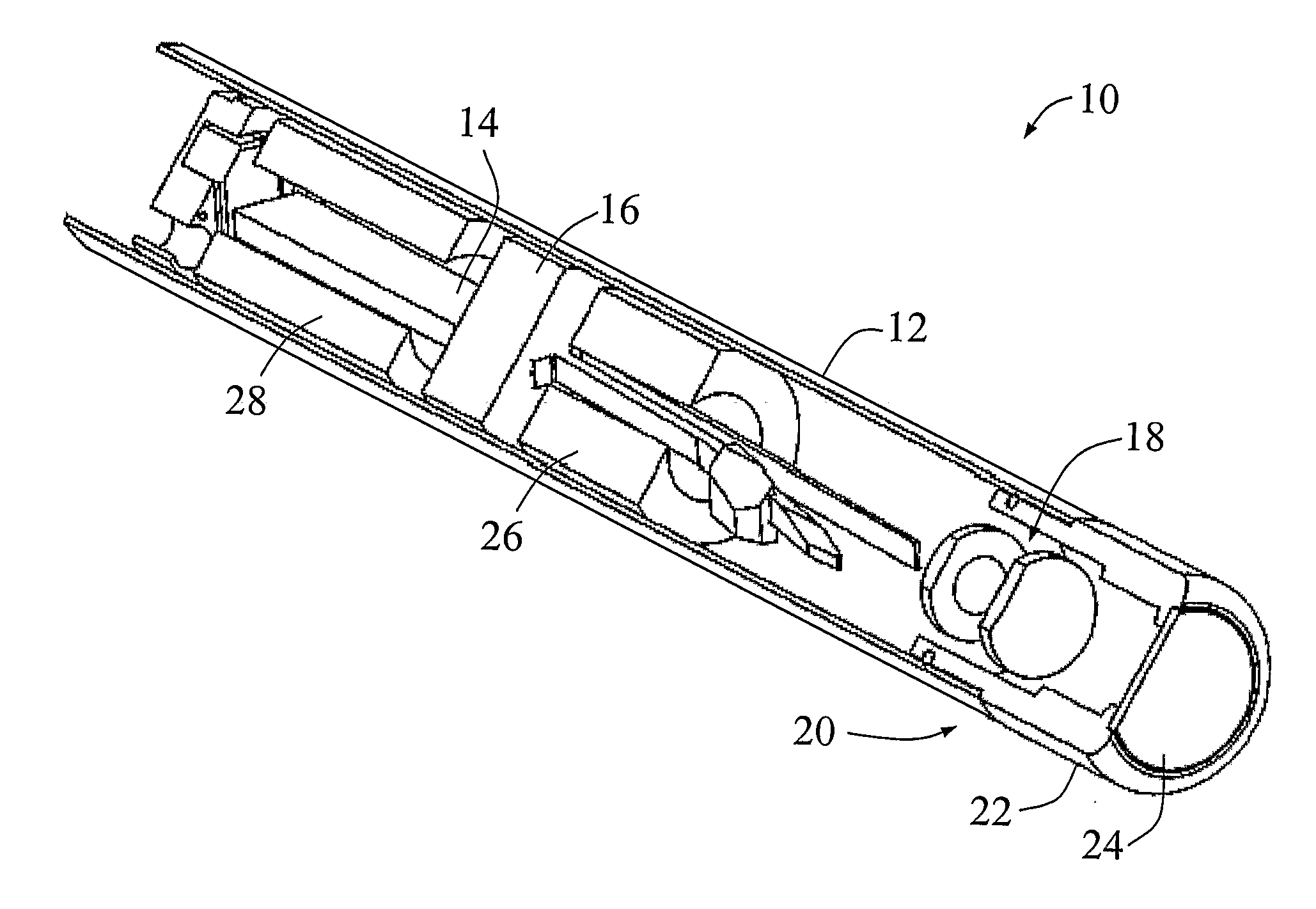
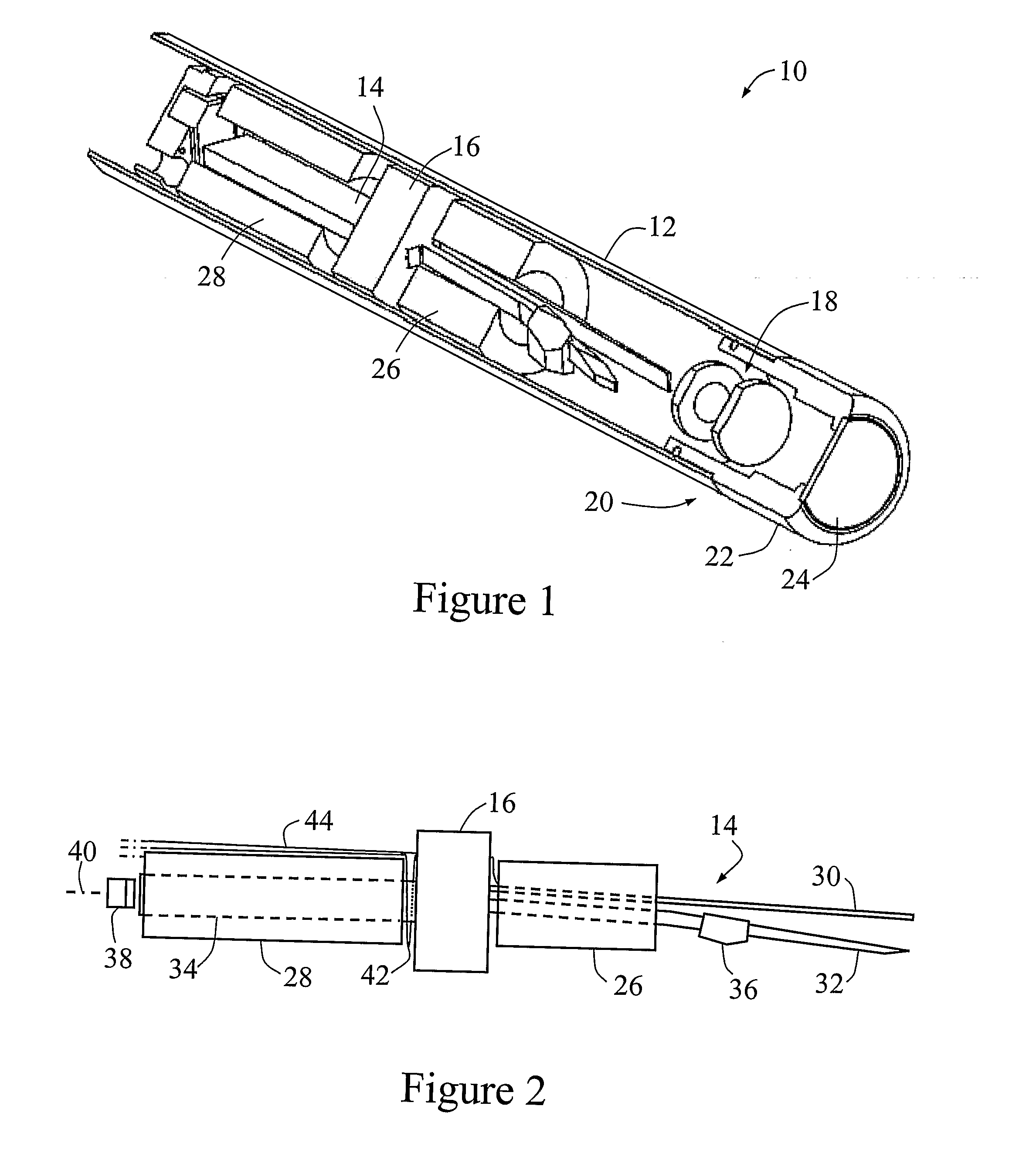
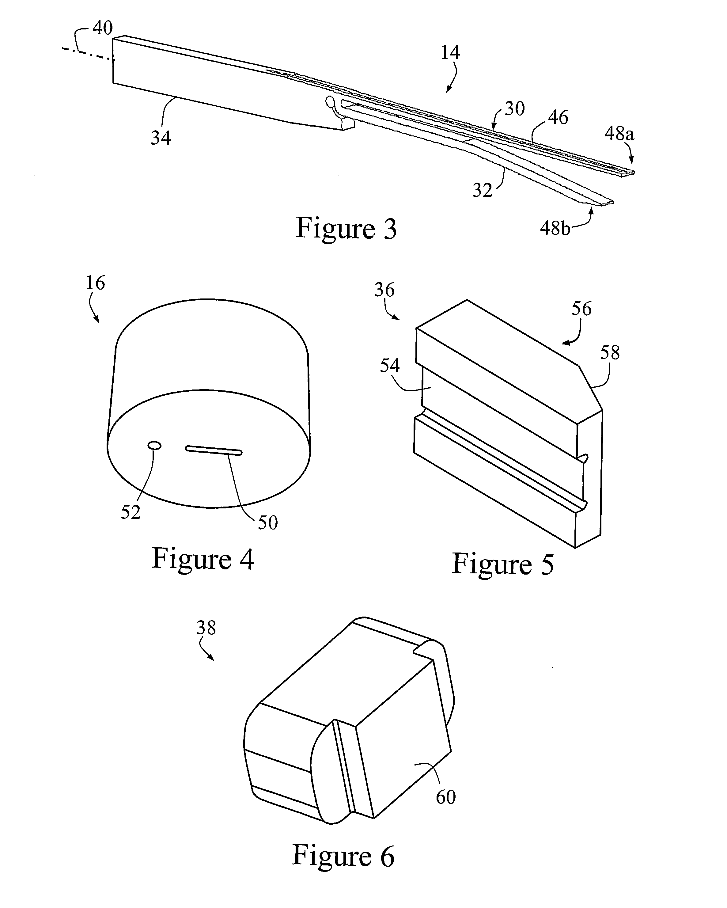
[0047] A scanning optical head according to the invention is shown in partial cut-away view generally at 10 in FIG. 1. The optical head 10 includes a casing 12 containing a fork 14 located in and held by a fork mount 16. The optical head 10 also includes, forward of the fork 14, a lens train 18. The forward end 20 of the casing 12 is closed by means of a cap 22 that includes a forwardly facing window or cover glass 24.

[0048] The optical head 10 has been constructed with an external diameter of less than but approximately equal to 5 mm (excluding casing 12) and a length of less than but approximately equal to 45 mm. However, another embodiment has been constructed with a diameter of approximately 3.5 mm (excluding casing 12) or 4.4 mm including the casing 12; in this embodiment the optical head 10 excluding casing has a length of at least 100 mm, with lengths of up to 300 mm when the casing is included and depending on application.

[0049] The fork 14, in use, supports and scans an op...

second embodiment

[0102] A fork 190, fork mount 192, drive coil 194 and stabilizing magnet 196 according to the invention are shown schematically in FIG. 12. These components are suitable for use in an optical head comparable to that of FIG. 1 but, unlike the optical head 10 of FIG. 1, this embodiment has only a single drive coil. A separate y-drive coil is omitted, and drive coil 194 performs the functions of both an x-drive coil and a y-drive coil. This embodiment does not include a biasing magnet (cf. biasing magnet 36). In other respects, however, fork 190, fork mount 192, drive coil 194, cable bundle 198 and optical fibre 199 are identical with fork 14, fork mount 16, x-drive coil 26, cable bundle 42 and optical fibre 44 of the embodiment of FIG. 1.

[0103] It is envisaged that, although it may be more difficult to obtain a linearity comparable to that of the two coil embodiment, the single coil embodiment will permit the construction of a more compact optical head.

[0104] The waveform of the driv...


PUM


Abstract

A scanning method and apparatus, the apparatus comprising a fork with first and second forwardly extending tines and a rearwardly extending counterweight member, a mount for supporting the fork at a point between the tines and the counterweight member, and a drive for effecting relative vibration between the tines to provide a fast scan and for driving the fork to provide a slow scan transverse to the fast scan.

Description

RELATED APPLICATION [0001] This application is based on and claims the benefit of the filing date of U.S. application Ser. No. 60 / 612,537 filed 24 Sep. 2004, the content of which is incorporated herein by reference in its entirety.FIELD OF THE INVENTION [0002] The present invention relates to a scanning apparatus and method, or particular but by no means exclusive application in optical systems including, for example, confocal or multiphoton systems. Such systems may be in the form of, for example, endoscopes, microscopes or endomicroscopes. BACKGROUND OF THE INVENTION [0003] Optical systems in general and endoscopes in particular may include a scanning system so that a two-dimensional image can be constructed of a sample. In some existing systems, this scanning system provides a raster scan comprising a fast scan (usually described as the x-scan) and a slow scan (usually described as the y-scan). [0004] One existing system is disclosed in WO 99 / 04301. A scanner is mounted in an opt...

Claims


Application Information

Patent Timeline
Patent Type & Authority Applications(United States)
IPC IPC(8): G02B26/10
CPCA61B1/00183G02B21/06G02B26/10G02B23/2469G02B23/2476G02B23/2423
Inventor ROSMAN, GAVAN EDMUNDBYRNE, CHRISTOPHER GERARDPATTIE, ROBERT ALAN
Owner OPTISCAN
Why Eureka
Try Eureka