Pneumatic radial tires

a radial tire and pneumatic technology, applied in the direction of tires, wheel components, tire beads, etc., can solve the problems of insufficient the occurrence of separation failure, and achieve the effect of ensuring strength and rigidity and excellent durability of the bead portion

Inactive Publication Date: 2005-08-16
BRIDGESTONE CORP
View PDF13 Cites 13 Cited by
  • Summary
  • Abstract
  • Description
  • Claims
  • Application Information

AI Technical Summary

Benefits of technology

[0012]It is, therefore, an object of the invention to provide a pneumatic radial tire having a carcass structure capable of easily conducting automatic building of an uncured tire, and controlling a pulling-out phenomenon of a carcass ply cord and sufficiently ensuring a strength and rigidity required for a bead portion to provide an excellent bead portion durability.

Problems solved by technology

During the running of the tire having such a radial carcass ply under loading, a large shearing strain is applied to the cord cut end of the turnup portion and hence the upper end part of the turnup portion results in the occurrence of separation failure.
On the other hand, the tire having the above carcass ply structure requires man power in the building of an uncured tire, which is out of the trend for labor saving and power saving and obstructs the building automation toward a near future.
In the pneumatic tire proposed in the former publication, however, since the return portion of the round trip cord is merely anchored in the bead core through the hard rubber, a phenomenon of pulling out the carcass ply cord from the bead core is caused as the running of the tire proceeds under an inflation of an internal pressure and hence a sufficient bead portion durability can not be obtained.

Method used


Image

  • Pneumatic radial tires
  • Pneumatic radial tires
  • Pneumatic radial tires

Examples


Embodiment Construction

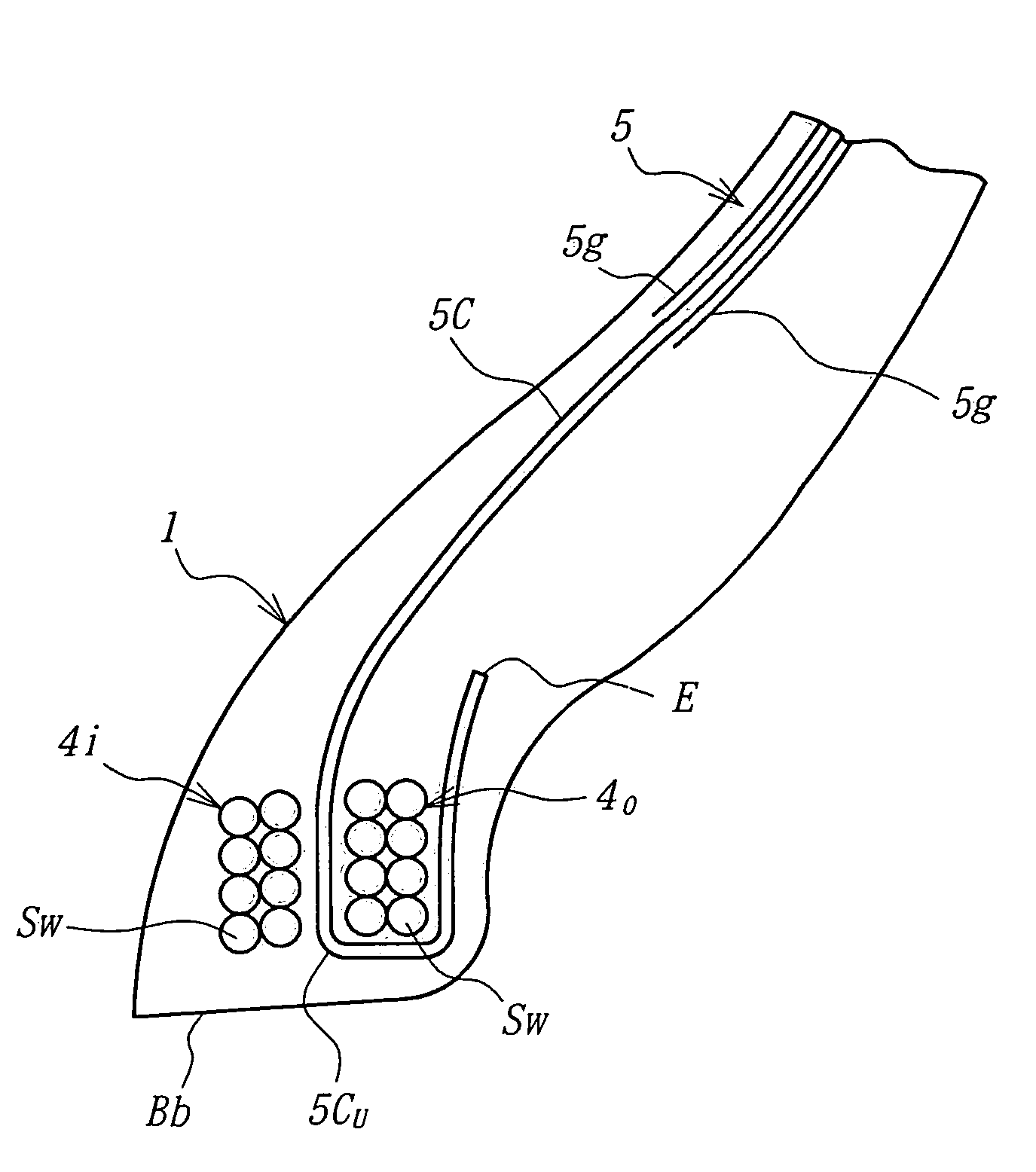
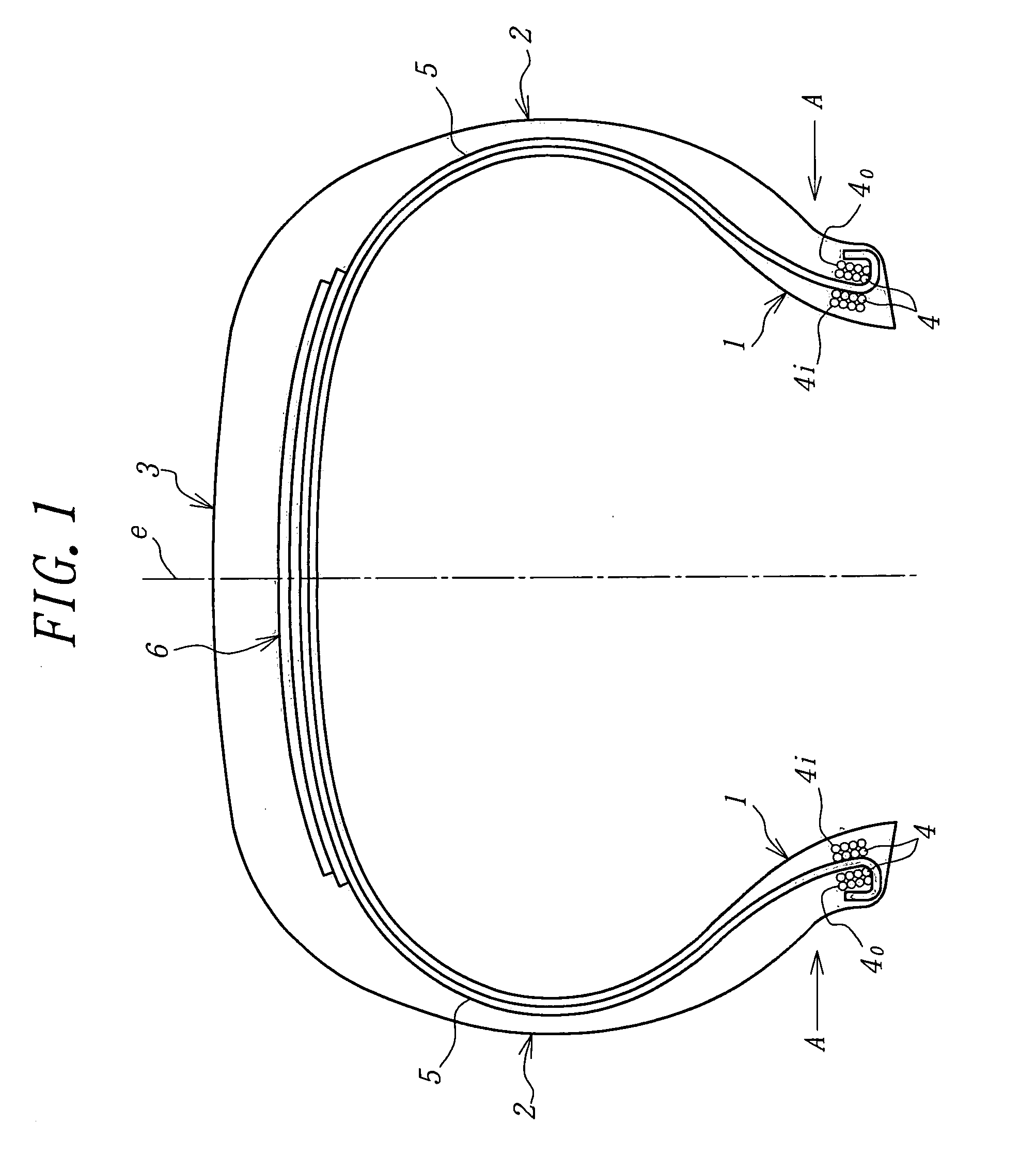
[0024]In FIG. 1 is shown a first embodiment of the pneumatic radial tire according to the invention, which comprises a pair of bead portions 1, a pair of sidewall portions 2, a tread portion 3 connecting the sidewall portions 2, and a radial carcass 5 extending between the pair of the bead portions 1 including two bead cores 4 therein and reinforcing the bead portions 1, sidewall portions 2 and tread portion 3. A belt 6 reinforcing the tread portion 3 is disposed on an outer circumference of the radial carcass 5 according to the custom. The two bead cores 4 are inner bead core 4i and outer bead core 4o arranged adjacent to each other in the widthwise direction of the tire. In FIG. 1, symbol e is an equatorial plane of the tire.

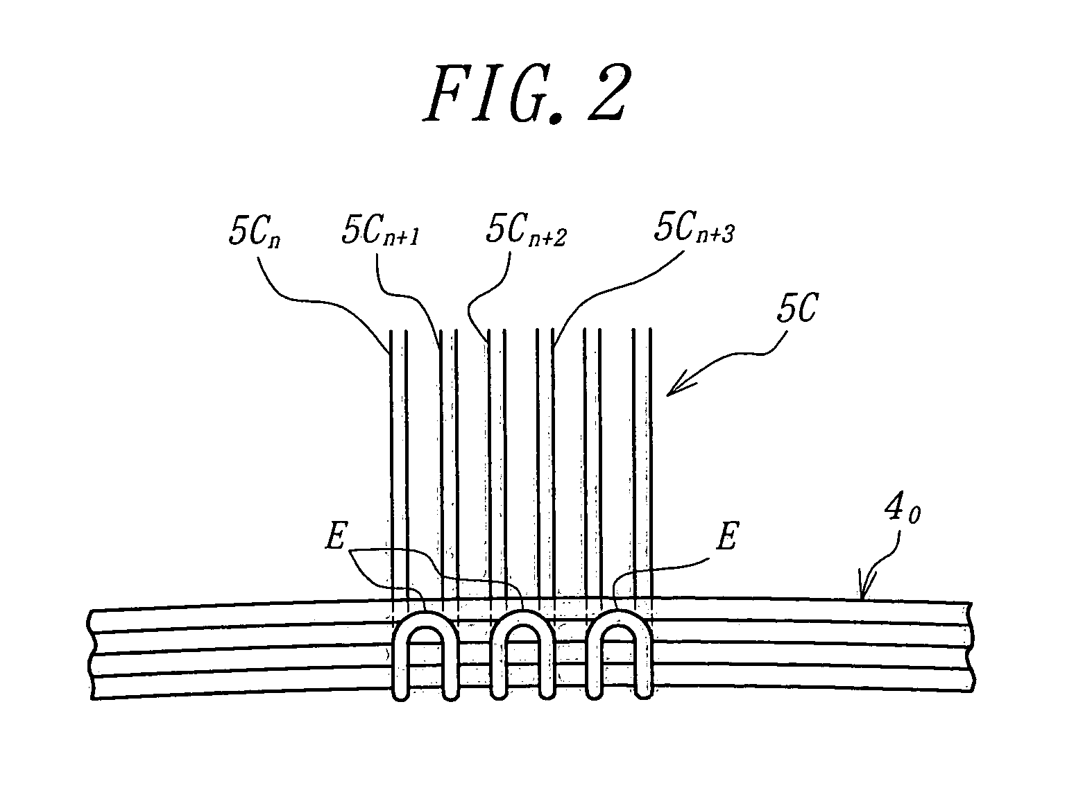
[0025]The radial carcass 5 is comprised of one or more rubberized plies having a radial cord arrangement (one ply in the illustrated embodiment). As shown in FIG. 2, a ply cord 5C of the radial carcass 5 is one or more continuous cords (one cord in the embodim...


PUM


Abstract

A pneumatic radial tire comprises a radial carcass extending between a pair of bead portions each including two bead cores therein and reinforcing a pair of sidewall portions and a tread portion, wherein the radial carcass is comprised of a rubberized ply of a continuous cord successively repeating round trip in at least one of the two bead cores as a pair between the pair of the bead portions along a circumference of the bead portion and a roundtrip return portion of the cord is existent in both the bead portions. In this case, at least one of the two bead cores has such a structure that one or more steel wires are arranged lengthwise and widthwise in radial and widthwise directions of the tire, and the cord of the carcass ply has a roundtrip return portion located through a side face of the bead core having the above structure so as to cover at least an innermost steel wire arrangement in the radial direction from an inner side in the radial direction of the tire.

Description

BACKGROUND OF THE INVENTION[0001]1. Field of the Invention[0002]This invention relates to a pneumatic radial tire, and more particularly to a pneumatic radial tire wherein a carcass ply cord is a continuous cord successively repeating roundtrip between a pair of bead portions in a circumferential direction of the tire. Particularly, the invention relates to a pneumatic radial tire capable of conducting automatic building in the production of an uncured tire and having an excellent bead portion durability.[0003]2. Description of Related Art[0004]In the carcass ply of the general-purpose pneumatic radial tire, it is well-known that organic fiber cords such as nylon cord, polyester cord and the like or inorganic fiber cords such as carbon fiber cord, steel cord and the like are used as a reinforcing member for a pair of bead portions, a pair of sidewall portions and a tread portion.[0005]The carcass ply comprised of a radial arrangement of the above cords has a turnup portion wound aro...

Claims


Application Information

Patent Timeline
Patent Type & Authority Patents(United States)
IPC IPC(8): B60C9/02B60C15/04B60C15/05B60C15/00B60C9/08
CPCB60C9/023B60C15/0018B60C15/0081B60C15/05B60C15/0027Y10T152/10819B60C2015/009
Inventor OGAWA, YUICHIRO
Owner BRIDGESTONE CORP
Why Eureka
Try Eureka