Cutting insert and milling cutter

a cutting insert and milling cutter technology, applied in the direction of shaping cutters, turning machine accessories, manufacturing tools, etc., can solve the problem that the prior art cutting insert b>12/b> will not be properly seated in the cylindrical milling cutter

Active Publication Date: 2005-08-16
ISCAR LTD
View PDF33 Cites 60 Cited by
  • Summary
  • Abstract
  • Description
  • Claims
  • Application Information

AI Technical Summary

Problems solved by technology

Therefore, the prior art cutting insert 12 will not be properly seated in the cylindrical milling cutter 50.

Method used


Image

  • Cutting insert and milling cutter
  • Cutting insert and milling cutter
  • Cutting insert and milling cutter

Examples


Embodiment Construction

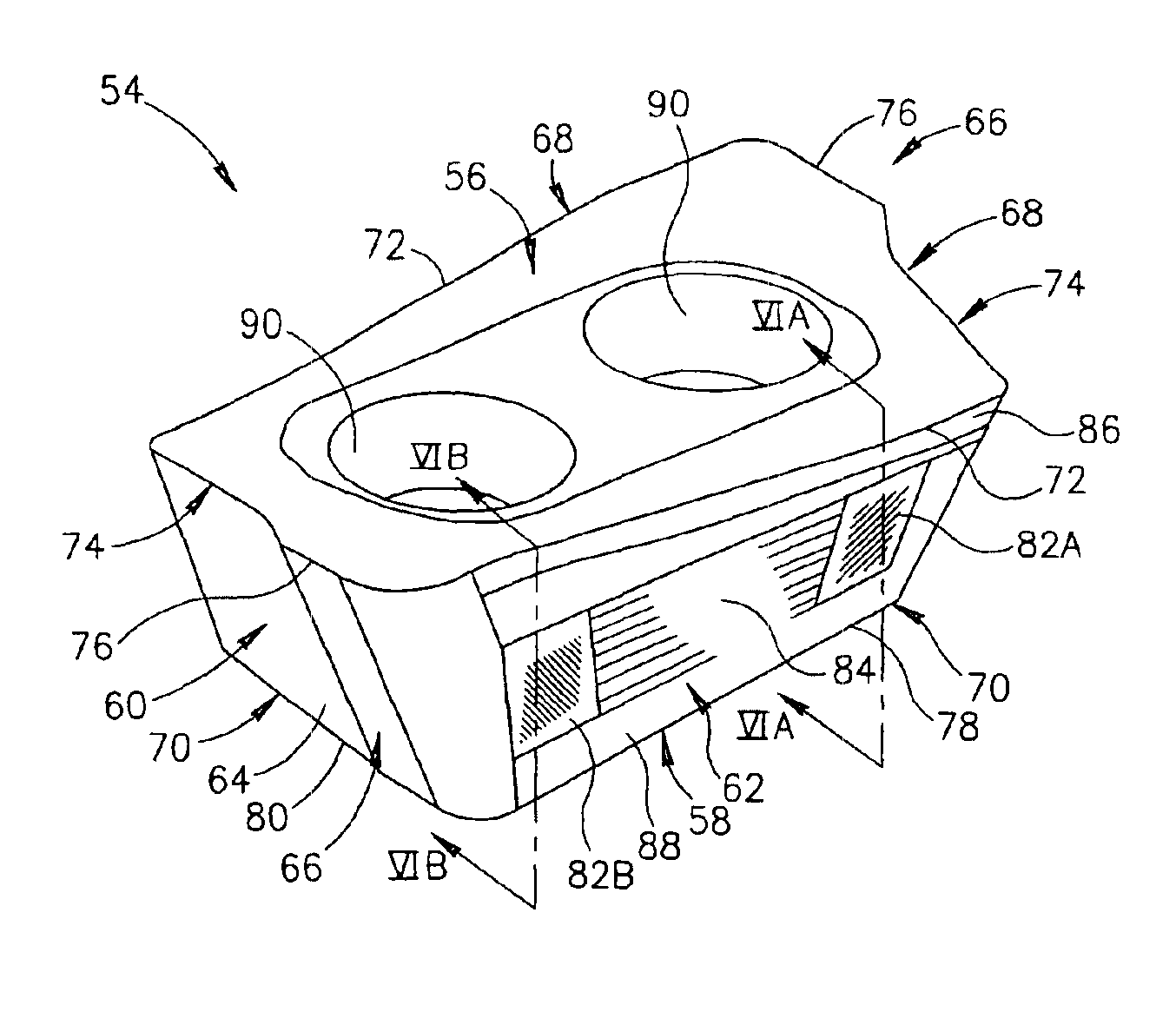
[0041]A cutting insert 54 in accordance with the present invention is shown in FIGS. 5 to 7. The cutting insert 54 is typically manufactured by form-pressing and sintering carbide powders. However, injection-molding techniques can also be used. The cutting insert 54 is generally rhomboidal in shape having a top surface 56, a bottom surface 58 and a peripheral side surface 60 extending between the top and bottom surfaces 56, 58. The peripheral side surface 60 comprises two major side surfaces 62 and two minor side surfaces 64. Although the invention is described with respect to cutting inserts that are generally rhomboidal in shape it is equally applicable to cutting inserts that are generally rectangular or square in shape. The two minor side surfaces 64 are provided with protruding portions 66. The major and minor side surfaces 62, 64 join the top surface 56 along a top edge 68, and the bottom surface 58 along a bottom edge 70. FIG. 7 shows an illustrative bottom view of the insert...


PUM

PropertyMeasurementUnit
angleaaaaaaaaaa
angleaaaaaaaaaa
angleaaaaaaaaaa

Abstract

A milling cutter has a cutter body having insert pockets, with cutting inserts seated in the insert pockets. Each insert pocket has adjacent side and rear walls generally transverse to a base, the side wall being provided with two spaced apart generally flat and non-coplanar side support surfaces. Each cutting insert has a pair of opposing major side surfaces including two spaced apart generally flat and non-coplanar abutment surfaces. Upper edges of the side support surfaces abut the abutment surfaces.

Description

FIELD OF THE INVENTION[0001]The present invention relates to replaceable indexable cutting inserts and milling cutters in general and in particular for milling square shoulders in a workpiece.BACKGROUND OF THE INVENTION[0002]A typical prior art milling cutter 10 having an axis of rotation A, and prior art cutting insert 12 for milling square shoulders in workpieces is shown in FIGS. 1 to 4. The prior art cutting insert 12 is generally rhomboidal in shape, having a top surface 14, a bottom surface 16, two major side surfaces 18 and two minor side surfaces 20. Some prior art inserts of this kind are also generally rectangular in shape. The two minor side surfaces 20 are provided with protruding portions 22. The major and minor side surfaces 18, 20 join the top surface 14 along a top edge 24, and the bottom surface along a bottom edge 26. FIG. 4 shows an illustrative bottom view of the prior insert of FIG. 1. The prior art milling cutter 10 has been removed so that the radial location ...

Claims


Application Information

Patent Timeline
Patent Type & Authority Patents(United States)
IPC IPC(8): B23C5/10B23C5/16B23C5/22B23C5/20B23C5/06
CPCB23C5/109B23C5/2221B23C2200/125B23C2200/126Y10T407/192Y10T407/1924Y10T407/1962Y10T407/23B23C2210/045B23C2210/168B23C2200/362B23C5/2213B23C5/22B23C5/10
Inventor SATRAN, AMIR
Owner ISCAR LTD
Why Eureka
Try Eureka