
Blade angle adjustment device for a stone cutter

a technology of angle adjustment device and stone cutter, which is applied in the direction of power-driven saws, sawing apparatus, manufacturing tools, etc., can solve the problems of difficult operation, not so ideal, and the adjustment of different slant angles of the blade is usually not accura

Inactive Publication Date: 2005-08-23
TSAO WEN HAI
View PDF8 Cites 40 Cited by
  • Summary
  • Abstract
  • Description
  • Claims
  • Application Information

AI Technical Summary

Benefits of technology

[0004]The present invention has a main object to provide a blade angle adjustment device for a stone cutter, which the blade angle is rapidly adjusted and / or backs to its original position. The blade is adjusted into a single accurate slant angle and the operation of the angle adjustment is very convenient to do.

Problems solved by technology

But it is difficult to operate and the results are not so ideal.
Further, the adjustment of different slant angle for the blade is usually not accurate and the slant angles of the tile edges are not so uniform.

Method used


Image

  • Blade angle adjustment device for a stone cutter
  • Blade angle adjustment device for a stone cutter
  • Blade angle adjustment device for a stone cutter

Examples


Embodiment Construction

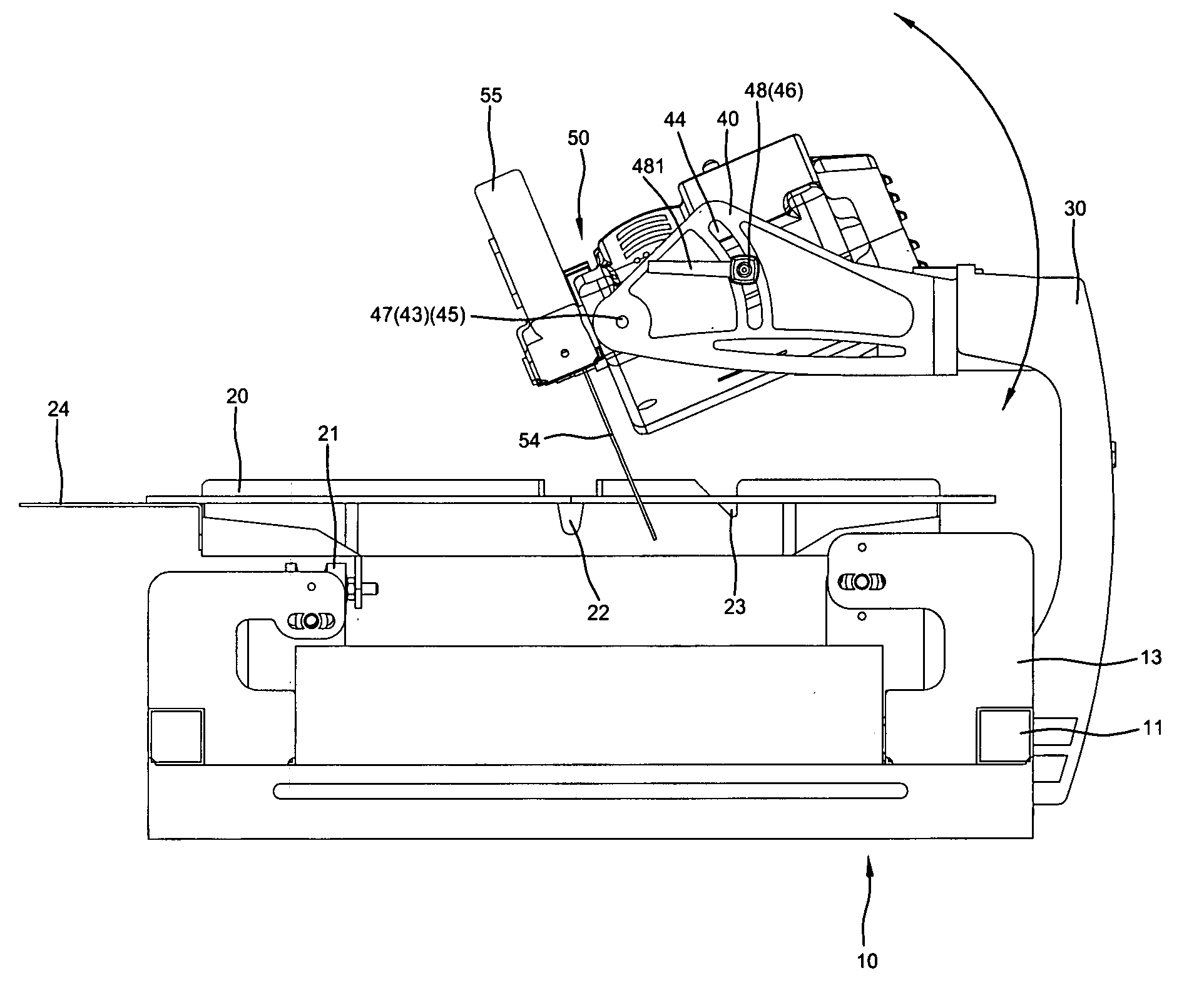
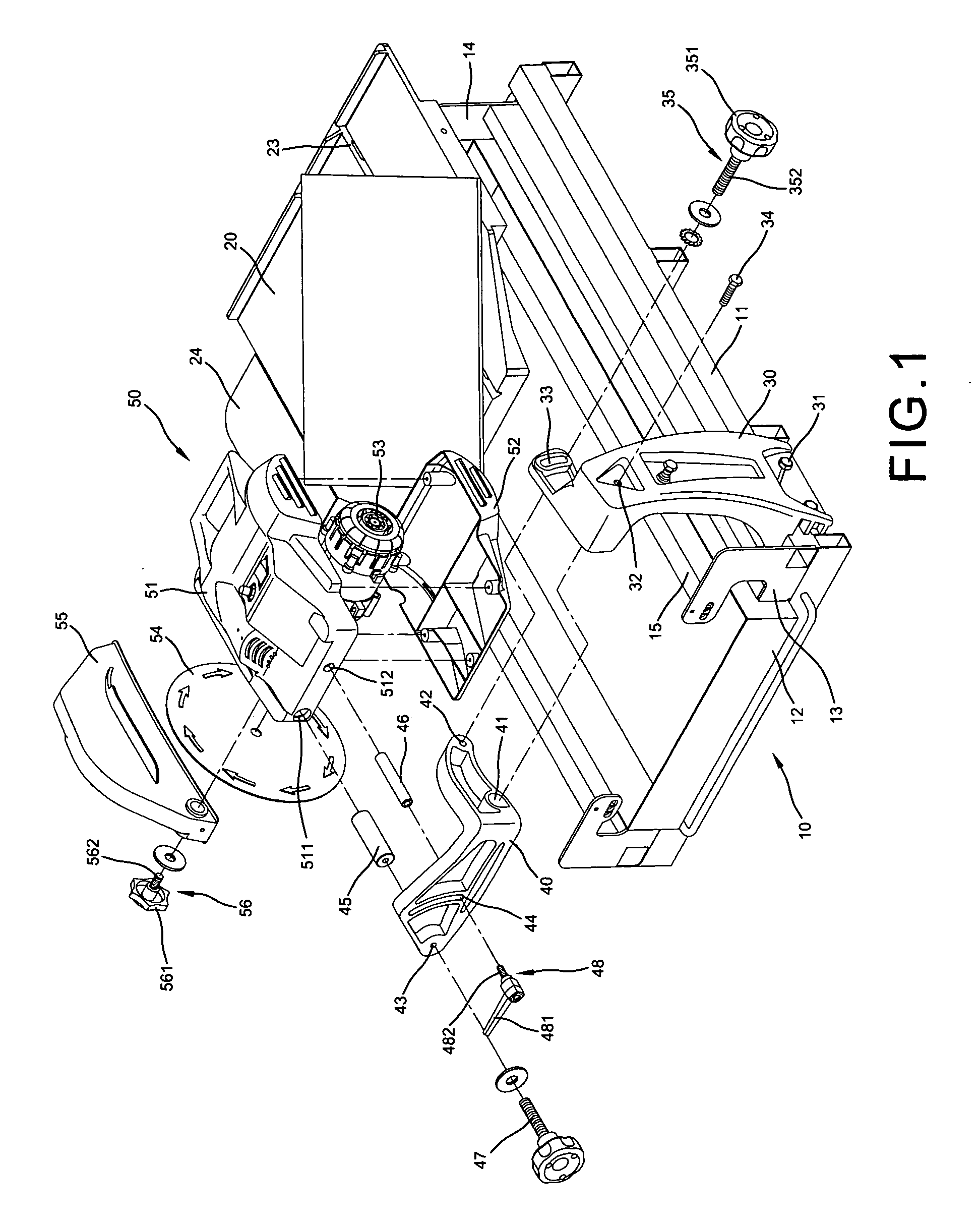
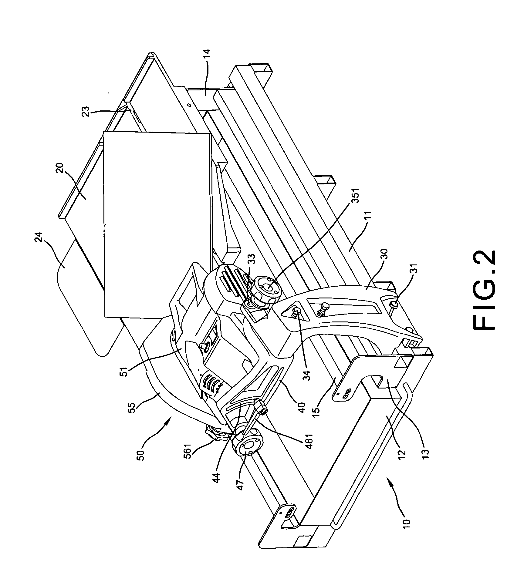
[0015]With reference to FIGS. 1 to 4 of the drawings, the blade angle adjustment device for a stone cutter of the present invention comprises a framed base 10 having a pair of outmost longitudinal bars 11, a rectangular frame 12, a pair of first sustaining plates 13 at front corners, a pair of second sustaining plates 14 at rear corners for supporting a pair of guide bars 15 respectively, a working table 20 having a plurality of rollers 21 on underside slidably disposed on the pair of guide bars 15, a vertical cutting groove 22 and slant cutting groove 23 spacedly formed in the upper surface, a tool plate 24 disposed on a right side of the base 10, a support arm 30 connected to a front portion of an outmost longitudinal bar 11 on left side of the base 10 by a screw 31 and having a screw hole 32 in a triangular depression and an oblong hole 33 in an lateral extension on the upper portion thereof, a roughly L-shaped link 40 having a pair screw holes 41 and 42 spacedly formed in a long...


PUM

PropertyMeasurementUnit
Angleaaaaaaaaaa
Angleaaaaaaaaaa

Abstract

A blade angle adjustment device for a stone cutter includes a framed base having a working table slidably disposed on the base including a vertical cutting groove and a slant cutting groove in upper surface, a tool plate and a support arm respectively secured to a lateral side thereof, a L-shaped link having pair of screw holes in a longitudinal portion engaged with a screw hole and oblong hole on the top of the support arm and secured by a screw and a first swivel lock, a screw hole and an arcuate slot in a transverse portion respectively engaged with the front ends of a large and a small internally threaded large and small connection rods and secured by a second swivel lock and a handled screw, a motor protected by an upper housing and a lower housing which is connected to the rear end of the connection rods and a guarded circular blade connected to an axis of the motor so that slides the first swivel lock in the oblong hole to define the elevational angle for the cutting mechanism and slides the small connection rod to define the slant angle for the blade up to 45 degree.

Description

BACKGROUND OF THE INVENTION[0001]The present invention relates to stone cutters and more particularly to a blade angle adjustment device for a stone cutter.[0002]A portable stone cutter facilitates the brick layers to cut the tiles or stones in order to fit the working site. The blade of prior art stone cutter is generally positioned perpendicular to cutting table such that the tiles or stones being cut appear a straight plane edge which is not fitting with one another at a corner of the wall. Thus, the tiles or stones must be cut a slant edge in predetermined angle to meet the requirement of close connection.[0003]Although, a blade angle adjustment device for the stone cutter appears in the market enabling to cut different slant edges for the tiles. But it is difficult to operate and the results are not so ideal. Further, the adjustment of different slant angle for the blade is usually not accurate and the slant angles of the tile edges are not so uniform.SUMMARY OF THE PRESENT INV...

Claims


Application Information

Patent Timeline
IPC IPC(8): B28D1/04B27B9/00B27B9/02B28D1/02B27B5/24
CPCB27B5/24B28D1/047Y10T83/8773
Inventor TSAO, WEN-HAI
Owner TSAO WEN HAI
Learn More