
Oval-shaped tube closure

a tube closure and oval head technology, applied in the field of containers, can solve the problems of affecting the appearance of the tube, the risk of damaging the decoration of the sleeve, and the complex method of making and using the tube with the oval head, so as to achieve the effect of enhancing the impression of the oval head tube and reducing the cos

Inactive Publication Date: 2005-08-23
CCL CONTAINER CORP
View PDF17 Cites 2 Cited by
  • Summary
  • Abstract
  • Description
  • Claims
  • Application Information

AI Technical Summary

Benefits of technology

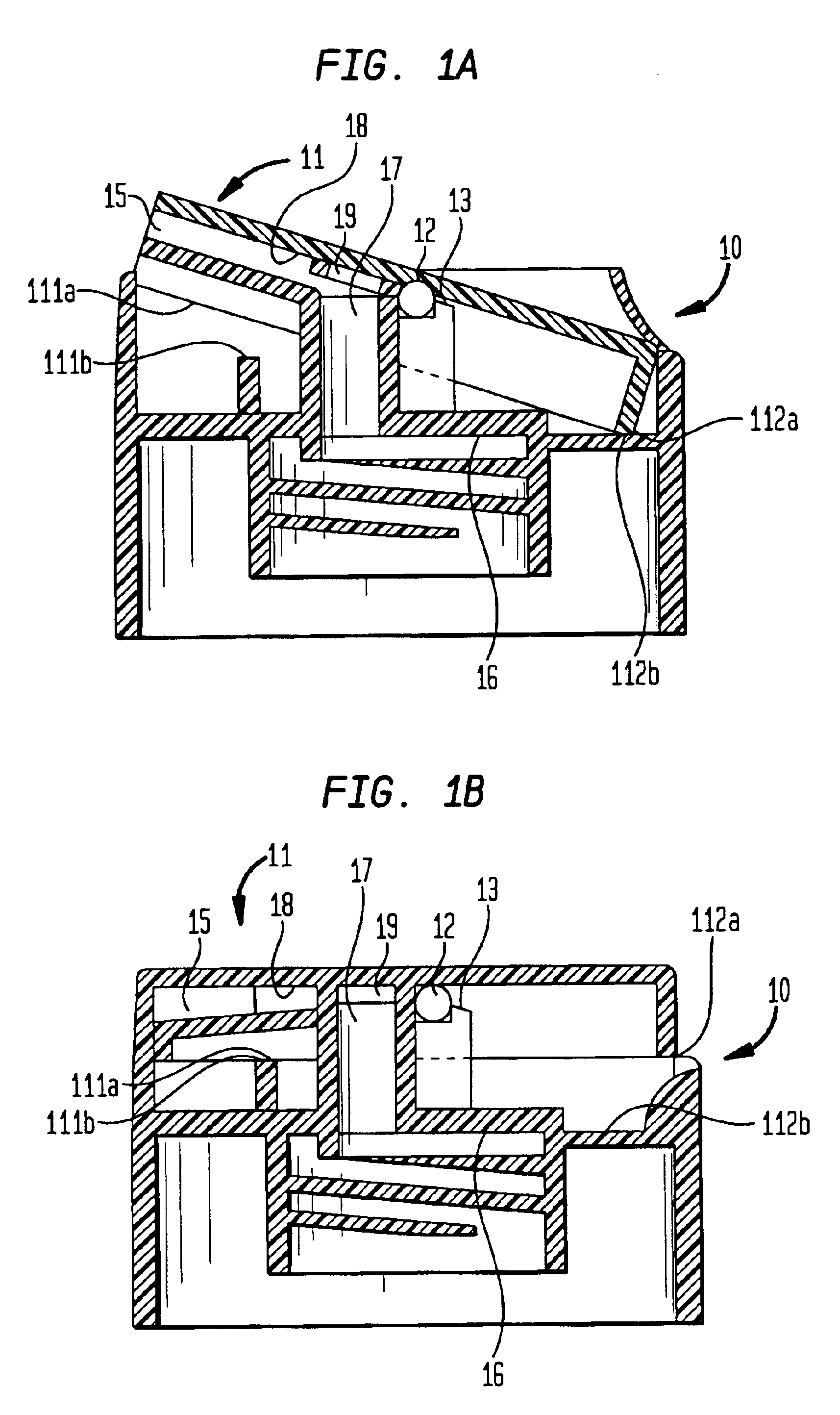
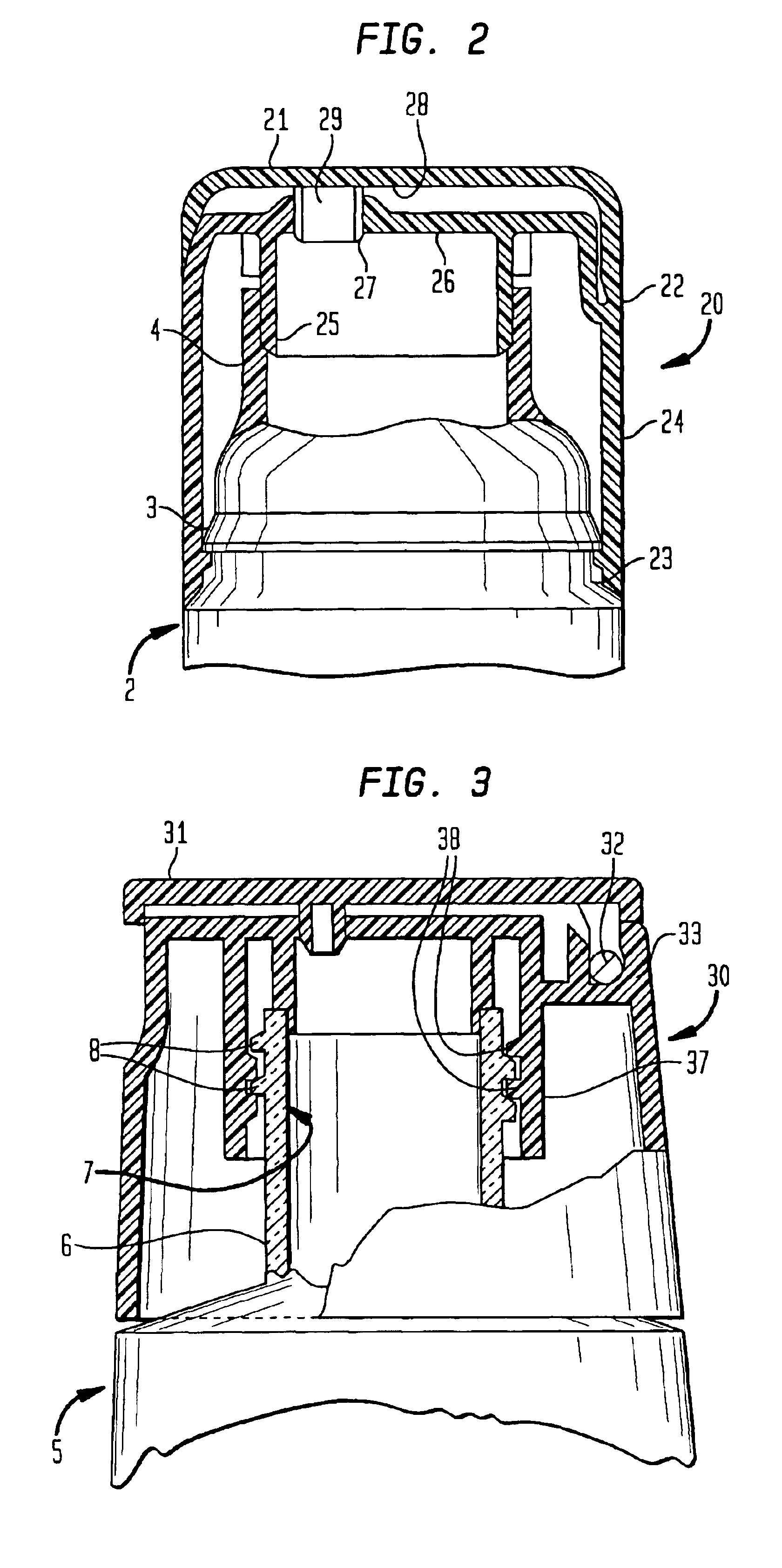
[0019]A dispensing closure is provided for a container for flowable material. The shape of the closure is defined by an external skirt which has a circular cross-sectional shape at its base that merges gradually to an oval-shaped face at the top of the closure. When combined with a standard circular-headed dispensing tube, the combination of this “round-to-oval” closure with the circular-headed tube appears to an ordinary observer to have oval-shaped cross sections throughout its length, rather than appearing to be a circular closure mounted to a circular tube. The use of the disclosed closure in combination with the standard circular-headed tube allows fabrication of visually distinctive packages for creams, lotions or other items typically packaged in dispensing tubes without the costs and wastage associated with fabricating oval-shaped tubes and closures.
[0023]In another preferred embodiment, the “round-to-oval” closure is combined with a standard circular-headed tube. The tube comprises a cylindrical sleeve having an open end and a closed end, said sleeve typically having the form of a right circular cylinder. The closed end of the tube is formed by a circular head molded onto the circular sleeve. The circular head also has a discharge port molded onto it. The “round-tooval” closure is attached to the discharge port of the tube so that the long axis of the oval face is substantially parallel to the straight edge formed by the crimped end of the tube. This combination of closure and tube appears to the ordinary observer to have a continuous cross-sectional oval shape throughout its length. This creates a distinctive visual impression of an oval tube at a substantially lower cost than would be incurred to manufacture an oval-headed tube and corresponding oval cap.
[0024]The impression of an oval-headed tube can be enhanced by decorating the partially flattened faces that are formed when the open end of the tube is crimped.

Problems solved by technology

The methods of making and using a tube with an oval head are more complex and costly than the method used with circular heads.
While feasible, this approach requires the purchase of an expensive oval-heading tool, with a cost of about $100,000 per diameter, and the purchase of specialized oval decorating mandrels instead of the more common circular mandrels.
There is also a risk of damaging the decoration on the sleeve due to the elevated temperatures and compression force involved in the compression-molding process.
This method suffers from the requirement for a secondary manufacturing step as well as from wastage of materials.

Method used


Image

  • Oval-shaped tube closure
  • Oval-shaped tube closure
  • Oval-shaped tube closure

Examples


Embodiment Construction

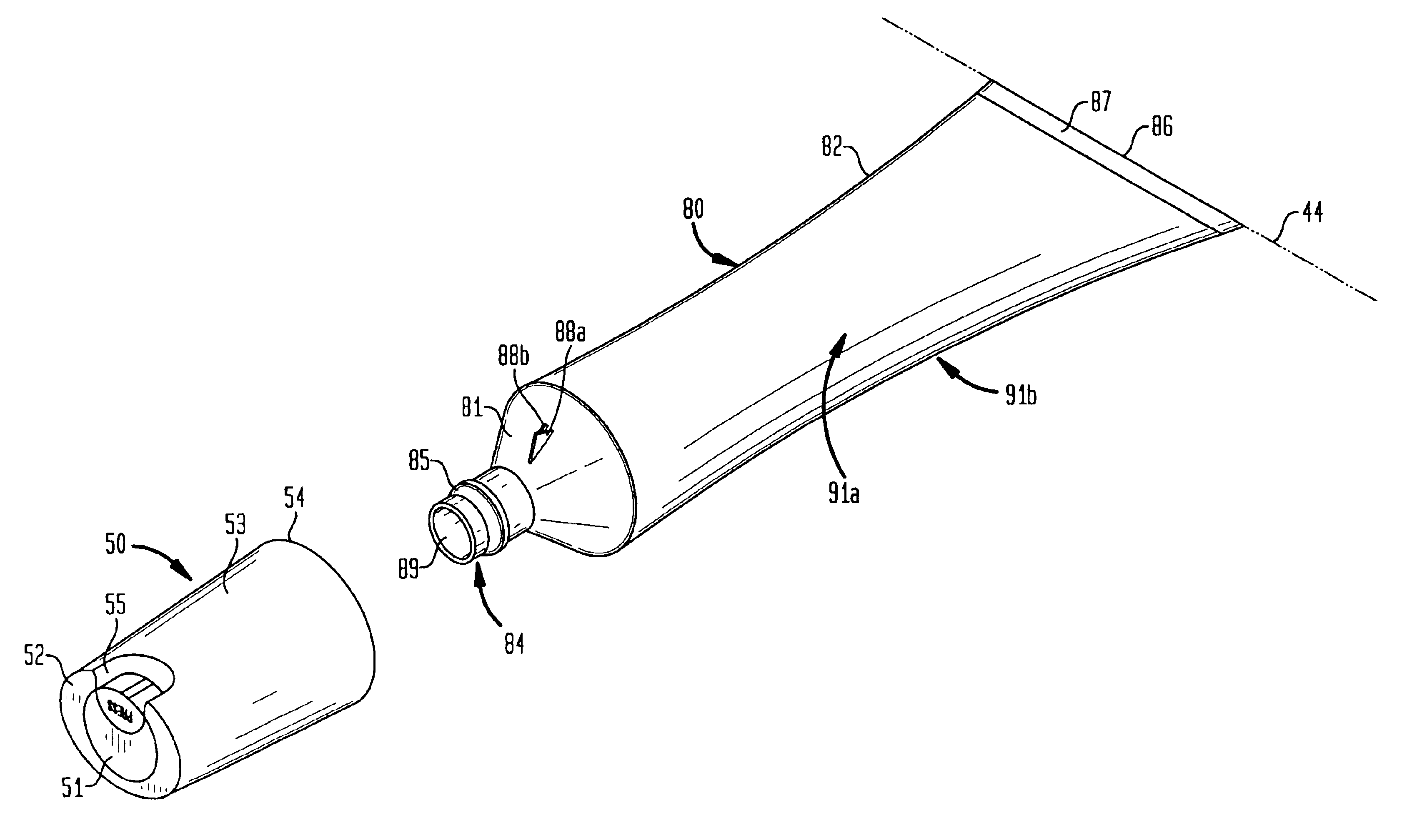
[0040]FIGS. 4A, 4B present exploded views of the preferred embodiment of the closure 50 in combination with a standard circular-headed tubular receptacle 80. In the embodiment of FIG. 4A, pushbutton-type closure 50 has a skirt 53 with a circular base 54 and an oval face 52 at its top. Actuator 51 is interfitted within oval face 52. Recess 55 is molded into skirt 53 to allow the adjacent end of actuator 51 to be conveniently depressed by the tip of a user's finger.

[0041]Closure 50 attaches to tubular receptacle 80 by means of a snap-on fitting 60. Tubular receptacle 80 comprises sleeve 82, circular head 81 and neck 84. Flange 85 is an annular structure protruding from the exterior of neck 84. Ribs 88a, 88b are provided on head 81 and serve to orient closure 50 with respect to tubular receptacle 80 and prevent rotation of closure 50 after it is secured to neck 84 of tubular receptacle 80. Head 81, neck 84, flange 85 and ribs 88a, 88b are formed as a single unit by compression-molding ...


PUM


Abstract

A dispensing closure is provided for attachment to the discharge port of a standard circular-headed tube. The closure comprises a skirt with a circular cross-sectional shape at its base that merges gradually to an oval-shaped face at its top. When the closure is attached to a standard circular-headed tube, with the long axis of the oval face oriented substantially parallel to the straight crimped edge of the filled tube, the combination of closure and tube appears to the ordinary observer to have a continuously oval cross-sectional shape throughout the length of the combination. The dispensing closure can be manufactured using typical injection-molding techniques, and may be adapted for use with dispensing mechanisms and attachment means known in the personal care products industry.

Description

CROSS-REFERENCE TO RELATED APPLICATIONS[0001]The present application is a divisional of U.S. application Ser. No. 09 / 784,900, filed on Feb. 16, 2001 now U.S. Pat. No. 6,631,833 , the disclosure of which is incorporated by reference herein.BACKGROUND OF THE INVENTION[0002]This invention relates to closures for containers, more particularly to closures that produce unique visual effects when combined with standard containers for personal care products.[0003]A variety of dispensing packages and containers have been developed for personal care products such as shampoos, lotions, etc., as well as for other materials. It is highly desirable that these dispensing containers be not only functional, but also have an aesthetic and distinctive appearance to attract the purchaser's eye and identify the product.[0004]Numerous examples of containers and dispensing closures that are both functional and visually distinctive are found in the prior art. The examples presented herein are representativ...

Claims


Application Information

Patent Timeline
IPC IPC(8): B65D35/44B65D35/00
CPCB65D35/44B65D2251/04B65D2251/065
Inventor HARRIMAN, RON E.CSASZAR, EDWARD F.
Owner CCL CONTAINER CORP
Learn More