Modular signal and power connection device

a module and power connection technology, applied in the direction of coupling device connection, coupling protective earth/shielding arrangement, tumbler/rocker switch, etc., can solve the problem that the electronic components used in audiovisual systems are subject to damag

Inactive Publication Date: 2005-08-23
CORE BRANDS
View PDF80 Cites 81 Cited by
  • Summary
  • Abstract
  • Description
  • Claims
  • Application Information

AI Technical Summary

Problems solved by technology

Electronic components used in audiovisual systems are subject to damage from electrical power surges.
Although power and signal cables might be physically separated outside of the interconnected components, over voltage conditions, arising from unstable line voltage, or lightning strikes, can propagate through multiple components in the absence of an appropriately designed system.

Method used


Image

  • Modular signal and power connection device
  • Modular signal and power connection device
  • Modular signal and power connection device

Examples


Embodiment Construction

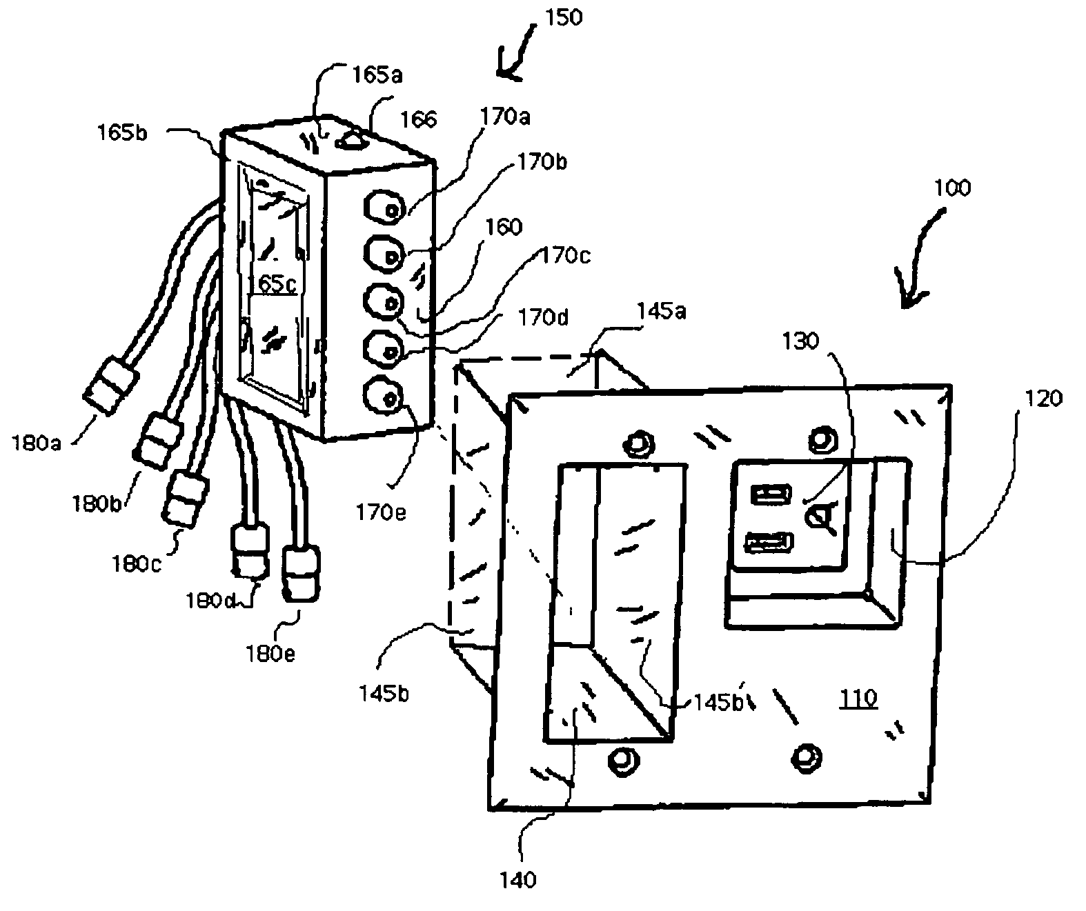
[0016]FIG. 1 illustrates in an exploded perspective view the connection box 100 and signal connection module 150 for use therewith. Connection box 100 has a front face 110 for mounting substantially flush with a surface, generally a room interior wall. Although signal connection module 150 is normally inserted into the connection box from the front face 110 side of connection box, it is shown behind the front face for illustration purposes. Connection box 100 has a first cavity 120 that extends inward, that is toward the interior of the wall, from the front face 110 for receiving a power connector in socket 130 disposed at the bottom of the cavity 130. Accordingly, socket 120 has electrically isolated input sockets for receiving plug prongs for connecting the corresponding line, neutral and ground wires thereto. Although not shown in this Figure it should be understood that connection box 100 also includes corresponding line, neutral and ground connection terminals for receiving bar...


PUM


Abstract

An electrical connection box for wall mounting provides a recessed external plug for receiving or transmitting power to electronic components. The connection box is configured to receive a variety of signal connection modules for interconnecting associated audio / visual electronics such as DVD players, displays and the like in adjacent apertures. The signal connection modules are inserted or extracted from the face of the connection box; replacing blanking plates, and is optionally recessed from the face of the box into the wall cut-out. The configuration and mating features of the box and modules also provides for a common and isolated ground reference for surge protection of the connected components.

Description

BACKGROUND OF INVENTION[0001]The current invention relations to wall mounted electrical junction box for power and low voltage signal connections of related electronic components.[0002]Electronic components used in audiovisual systems are subject to damage from electrical power surges. Numerous technologies and designs exist for either disconnecting equipment from such damaging conditions, or shunting the power to a ground connection via a nonlinear component. However, effective implementation of the schemes and designs requires interconnected components to be connected with a single ground source.[0003]Moreover, typical audiovisual systems utilizes multiple powered components, which are interconnected to receive and transmit relatively low voltage signals. To the extent that some of these components are physically separated from other components, for example the visual display unit for home theater system might be located across the room from a cabinet containing the DVD player or ...

Claims


Application Information

Patent Timeline
Patent Type & Authority Patents(United States)
IPC IPC(8): H01R12/00H01R13/627H01R13/658
CPCH01R13/6276H01R13/741H01R27/02
Inventor HOOPES, GERALD B.NEWELL, STEVEN
Owner CORE BRANDS
Why Eureka
Try Eureka