

Method and system for airborne meter communication
a technology of airborne meter and communication method, which is applied in the direction of electric devices, wireless architecture, instruments, etc., can solve the problems of requiring hundreds of employees, a manpower-intensive approach of the employed person, and the number of problems faced by the employed person, etc., to achieve cost saving, cost saving, and high accuracy
- Summary
- Abstract
- Description
- Claims
- Application Information
AI Technical Summary
Benefits of technology
Problems solved by technology
Method used
Image

Examples
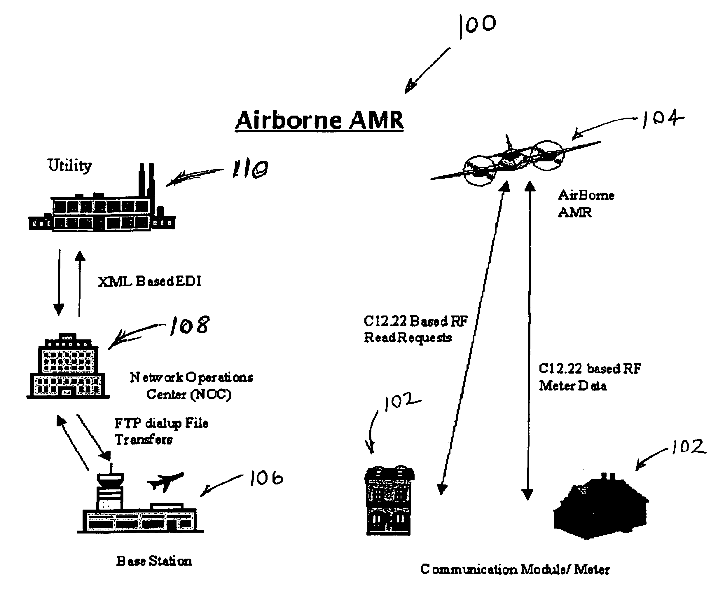
exemplary embodiment 100
[0044]The RF design of the first exemplary embodiment 100 allows operations from 255 MHz to 5.7 GHz without changing the data protocol and data rates or the spread spectrum frequency hop RF modulation approach. It is understood that the RF design may be modified to extend the frequency band down to 218 / 219 MHz for use in some geographic areas. However, presently, this band does not allow either frequency hopping modulation schemes or the bandwidth to support a high data rate. Although, it is understood that future developments of this invention will permit the use of this frequency band.
[0045]As shown in FIG. 6, airborne platform 104 of the first exemplary embodiment is flown according to a computer generated flight path 126 through a predetermined set of waypoints and over a corresponding population of meters 102. As airborne platform 104 flies to each waypoint over each corresponding meter 102, platform 104 queries each meter 102, in a manner that is similar to pinging a computer ...
first exemplary embodiment
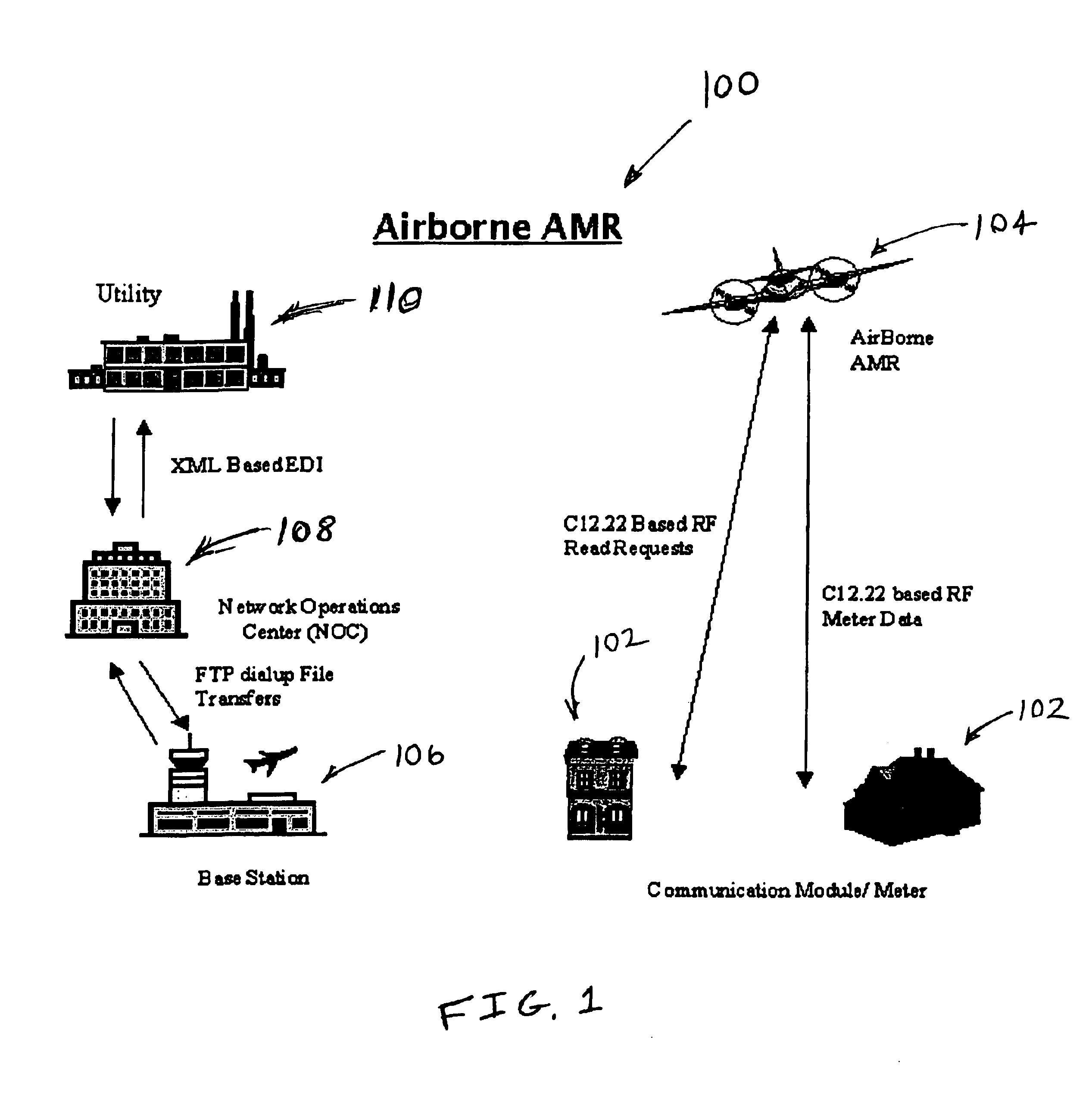
[0059]As explained above, the SE-240 meter is modified in the first exemplary embodiment by rotating it 180 degrees so that the RF module 134 resides on the upper half of meter 102 when it is connected to the SE-240 meter. This allows the antenna in RF module 134 to be optimally positioned relative to the SE-240 to communicate with airborne platform 104.
[0060]RF module 134 provides the basis to both easily command data downloads from the meter 102 to the airborne platform 104, to receive the information in the airborne platform 104 and to forward the meter data directly to the utility company or to a second party meter reading contractor.
[0061]RF module 134 includes a microprocessor that controls the module operations. The microprocessor controls the transfer of data between RF module 134 and the SE-240 meter. The microprocessor also controls communications between the RF module 134 and airborne platform 104. The processing power required for the microprocessor depends at least part...
PUM
 Abstract
Description
Claims
Application Information