
Method for obtaining head positions in magnetic data writing apparatus

a writing apparatus and magnetic data technology, applied in the direction of maintaining head carrier alignment, track selection/addressing details, instruments, etc., can solve the problems of difficult to accurately write servo patterns, impaired spindle motor rotation accuracy, and low throughput, so as to facilitate shortening the period of time for writing

Active Publication Date: 2005-08-23
FUJI ELECTRIC CO LTD
View PDF14 Cites 12 Cited by
  • Summary
  • Abstract
  • Description
  • Claims
  • Application Information

AI Technical Summary

Benefits of technology

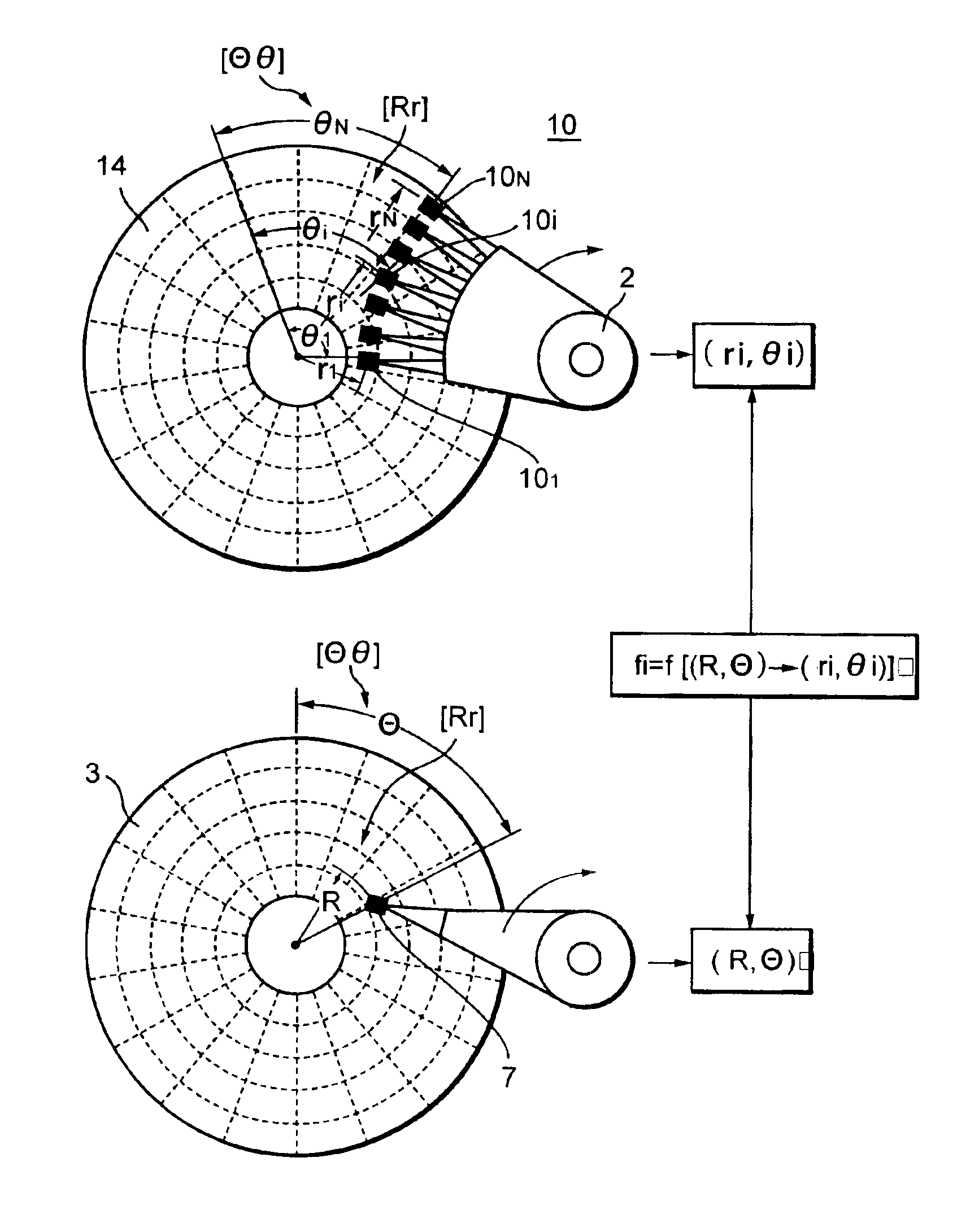
[0025]In view of the foregoing, it would be desirable to provide a method of obtaining the head positions in a disk servo writer, which stacks an original disk and a plurality of copy disks and causes a plurality of servo heads arranged on each surface of the copy disks simultaneously to write the servo patterns obtained based on the servo data read out by a read-only head from the original disk to each surface of the copy disks, for easily obtaining the relative positional relationships between the read-only head on the original disk and the servo heads on the surfaces of the copy disks.
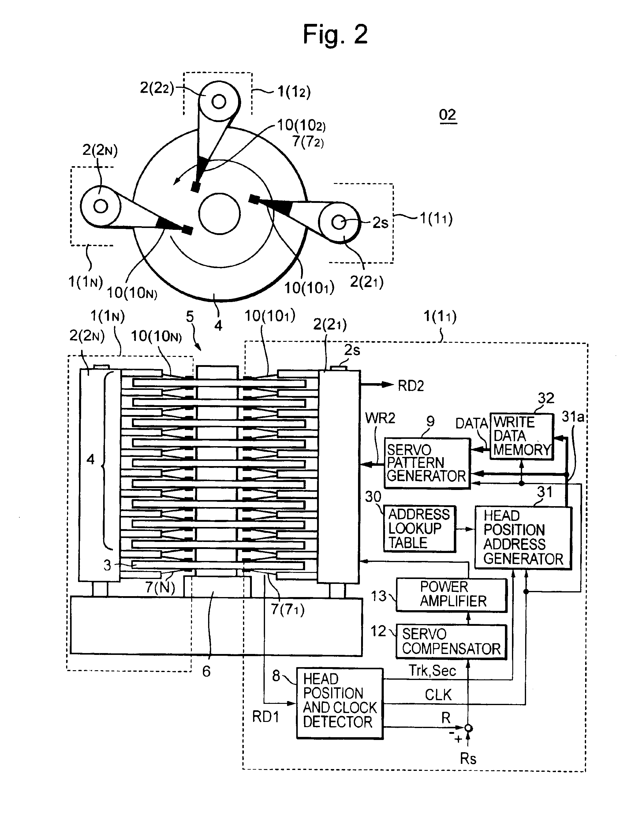
[0027]The method includes mounting third magnetic disks (calibration disks) on the shaft of the spindle motor in place of the copy disks, prior to writing magnetic data to the copy disks. The calibration disks store calibration data, which facilitates making the servo heads accurately read therefrom first addresses indicating the addresses of the tracks and sectors, where the servo heads are on the surfaces of the calibration disks.
[0030]The method includes mounting calibration disks on the shaft of the spindle motor in place of the copy disks, prior to writing magnetic data to the copy disks. The calibration disks store calibration data, which facilitates making the servo heads accurately read therefrom first addresses indicating the position addresses of the tracks and sectors where the servo heads are on the surfaces of the calibration disks.
[0033]The method according to the invention for obtaining the positions of magnetic heads in a disk servo writer facilitates obtaining the relative positional relationships between a plurality of servo heads on the surface of a copy disk and a read-only head and causing the servo heads to write magnetic data to the respective track ranges on the copy disk, to which the servo heads are assigned. Therefore, the method according to the invention facilitates shortening the period of time for writing magnetic data to the copy disks.

Problems solved by technology

As the track density on a magnetic disk is improved, the time for servo pattern writing becomes longer, causing lower throughput.
Although it is possible to shorten the time for servo pattern writing by increasing the rotational speed of the disks, there is a tradeoff between shortening the writing time by faster disk rotation and mechanical vibrations that become more vigorous with the increased speed and make it harder to write the servo patterns accurately.
However, the accuracy of the spindle motor rotation is impaired by increasing the number of disks in the stack since a heavier load is exerted on the spindle motor.
Thus, it becomes increasingly difficult to mount the magnetic heads within the predetermined range of accuracy, as the number of stacked magnetic heads increases.
However, it takes time to detect the positions of the magnetic heads.

Method used


Image

  • Method for obtaining head positions in magnetic data writing apparatus
  • Method for obtaining head positions in magnetic data writing apparatus
  • Method for obtaining head positions in magnetic data writing apparatus

Examples


Embodiment Construction

[0045]Now the invention will be described in detail hereinafter with reference to the accompanied drawing figures, which illustrate the preferred embodiments of the invention.

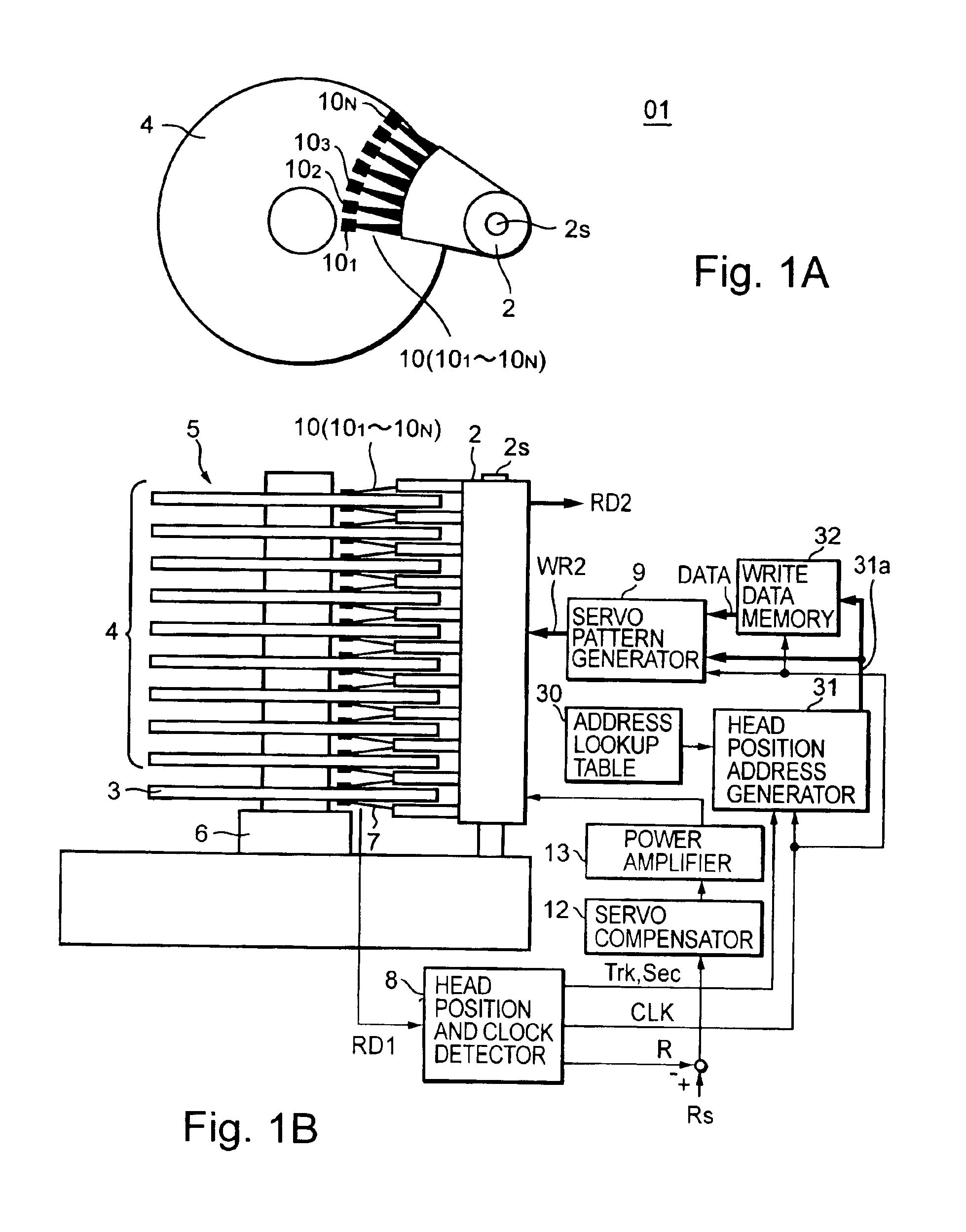
[0046]FIG. 1 is a block diagram schematically showing the configuration in a disk servo writer 01, to which a method according to a first embodiment of the invention is applied for obtaining the head positions therein.

[0047]In the disk servo writer 01, a disk stack unit 5 including a plurality (nine in FIG. 1) of stacked magnetic disks (copy disks) 4, to which the servo data is to be written, and an original disk 3 below disk stack unit 5 are mounted on the shaft of a spindle motor 6 rotating at several thousand rpm.

[0048]For each copy disk 4, N magnetic servo heads 10 (101 through 10N), are arranged radially like a fan on each copy disk surface. Hereinafter, servo heads 101 through 10N arranged radially like a fan on a disk surface will be referred to collectively as a “fan-shaped head 101-10N”.

[0049]A rotary ...


PUM


Abstract

A method for obtaining relative positional relationships between a read-only head for reading data from an original disk and servo heads on each surface of magnetic disks (copy disks), in a magnetic data writing apparatus (disk servo writer) that stacks copy disks and an original disk to rotate the disks unitarily. The apparatus includes a rotary positioner on the periphery of the copy disks and a read-only disk, stacking the read-only head and servo heads rotatably. The apparatus causes the servo heads simultaneously to write servo data to respective assigned track ranges. The method includes stacking calibration disks storing servo data in place of the copy disks in a coaxial relation with the read-only head, in advance of writing magnetic data to the copy disks. Using the calibration disks, relative positional relationships are obtained as between the address that the read-only head reads out from the original disk and the addresses that servo heads read out from calibration disks at the same time that the read-only head reads out the address thereof.

Description

BACKGROUND OF THE INVENTION[0001]1. Field of the Invention[0002]The invention relates to a magnetic data writing apparatus called a “disk servo writer”, for writing servo patterns for detecting magnetic head positions, writing ID patterns for identifying disks, and writing programs into magnetic disks that initially contain no data, to produce magnetic disk products including data written therein upon requests of clients. Hereinafter, the magnetic data writing apparatus will be referred to as the “disk servo writer.”[0003]Specifically, the invention relates to a disk servo writer for stacking a plurality of magnetic disks (hereinafter referred to as “copy disks”), to which magnetic data is to be transferred, and a magnetic disk (hereinafter referred to as an “original disk”) storing the magnetic data to be transferred to the copy disks and / or the magnetic data referred to in writing data to the copy disks. The disk servo writer rotates the copy disks and the original disk concentric...

Claims


Application Information

Patent Timeline
IPC IPC(8): G11B5/49G11B5/596G11B21/10
CPCG11B5/4976G11B5/59633G11B5/5578
Inventor ONO, TAKUYASATO, KIMINORI
Owner FUJI ELECTRIC CO LTD
Learn More