
Cable installation system and related methods

a cable installation and cable technology, applied in the direction of cable arrangement between relatively moving parts, distance measurement, ways, etc., can solve the problem of saving installer time in the installation process, and achieve the effect of reducing waste of cables and facilitating the installation process

Inactive Publication Date: 2005-08-30
COMMSCOPE INC
View PDF29 Cites 9 Cited by
  • Summary
  • Abstract
  • Description
  • Claims
  • Application Information

AI Technical Summary

Benefits of technology

[0008]In view of the foregoing background, it is therefore an object of the present invention to provide a cable installation system and related methods which facilitate the installation process and reduce cable waste.
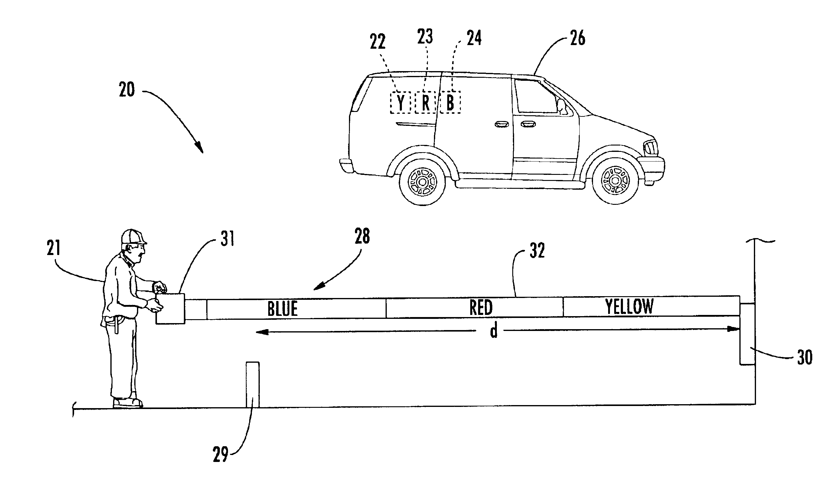
[0009]This and other objects, features, and advantages in accordance with the present invention are provided by a cable installation system for use by a cable installer which may include a plurality of cable dispensers having different lengths of cable. In particular, each cable dispenser may also have a non-numeric, length-identifying marking associated therewith corresponding to the length of cable. Furthermore, the system may also include a cable dispenser indicator device for use by the installer to determine a distance between first and second locations, such as a cable tap and a subscriber interface. The cable dispenser indicator device may also provide an indication to the installer of the non-numeric, length-identifying marking corresponding to the determined distance so that the cable installer can select the corresponding cable dispenser from the plurality thereof.
[0011]Accordingly, the system of the present invention significantly simplifies the process of selecting the appropriate cable length by reducing the “guesswork” the installer will have to exercise. That is, the installer may carry the various cable dispensers in his truck and, based upon the indication (i.e., color, symbol, etc.) provided by the cable dispenser indicator device, simply select the appropriate dispenser having the indicated marking thereon. Not only may this lead to a reduction in wasted cable, but it may also save the installer time in the installation process.
[0013]To further facilitate the installation process, each length of cable may have at least one respective connector connected to an end thereof. That is, the installer may bring dispensers with pre-connectorized cables to an installation site so he is not required to cut and / or splice cables and install connectors on site. This may further reduce the amount of time required for installation and thus reduce costs to the service provider since more installations can be performed without hiring more installers.

Problems solved by technology

Not only may this lead to a reduction in wasted cable, but it may also save the installer time in the installation process.

Method used


Image

  • Cable installation system and related methods
  • Cable installation system and related methods
  • Cable installation system and related methods

Examples


Embodiment Construction

[0022]The present invention will now be described more fully hereinafter with reference to the accompanying drawings, in which preferred embodiments of the invention are shown. This invention may, however, be embodied in many different forms and should not be construed as limited to the embodiments set forth herein. Rather, these embodiments are provided so that this disclosure will be thorough and complete, and will fully convey the scope of the invention to those skilled in the art. Like numbers refer to like elements throughout. Prime and multiple prime notation are used to indicate similar elements in alternate embodiments.

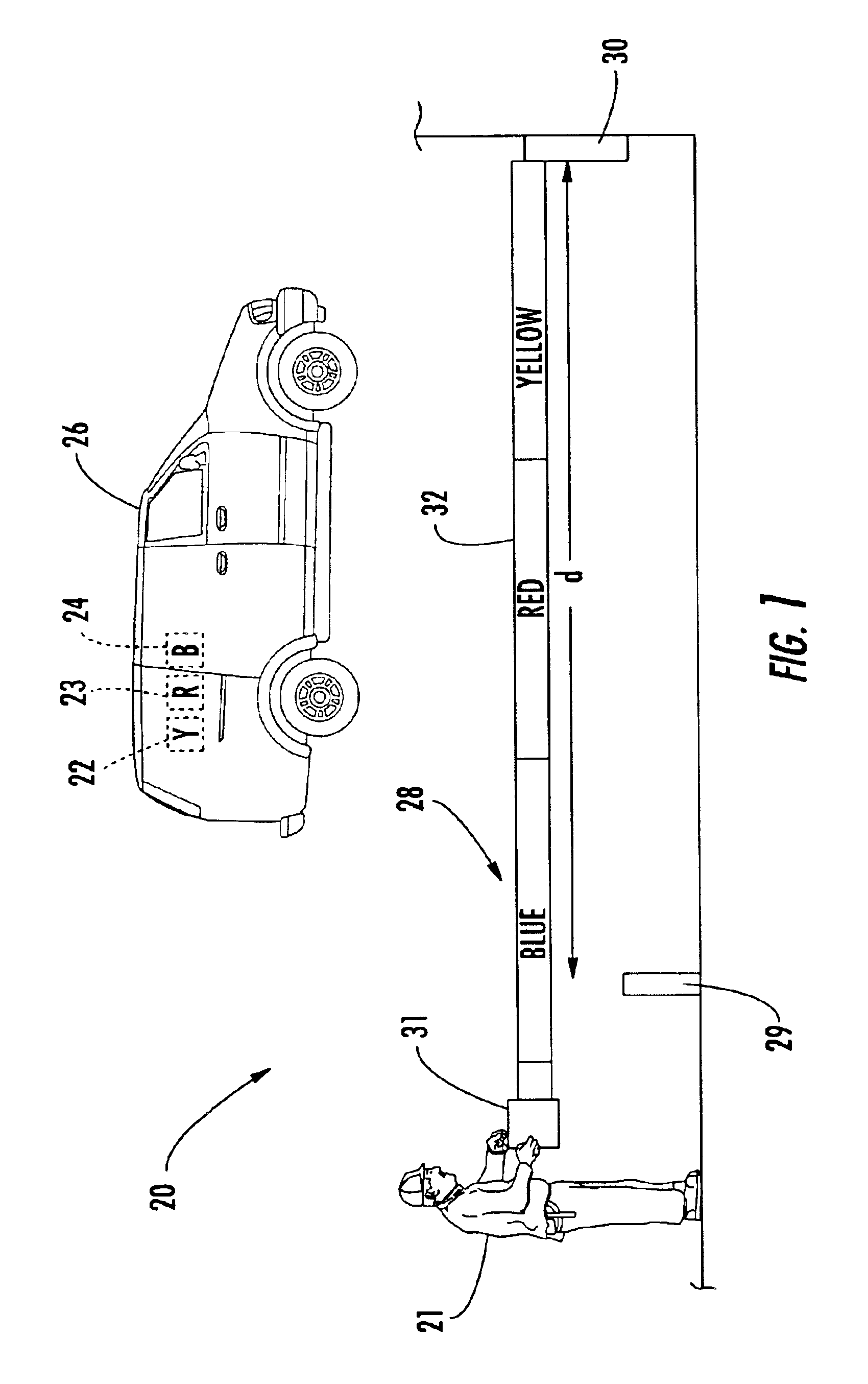
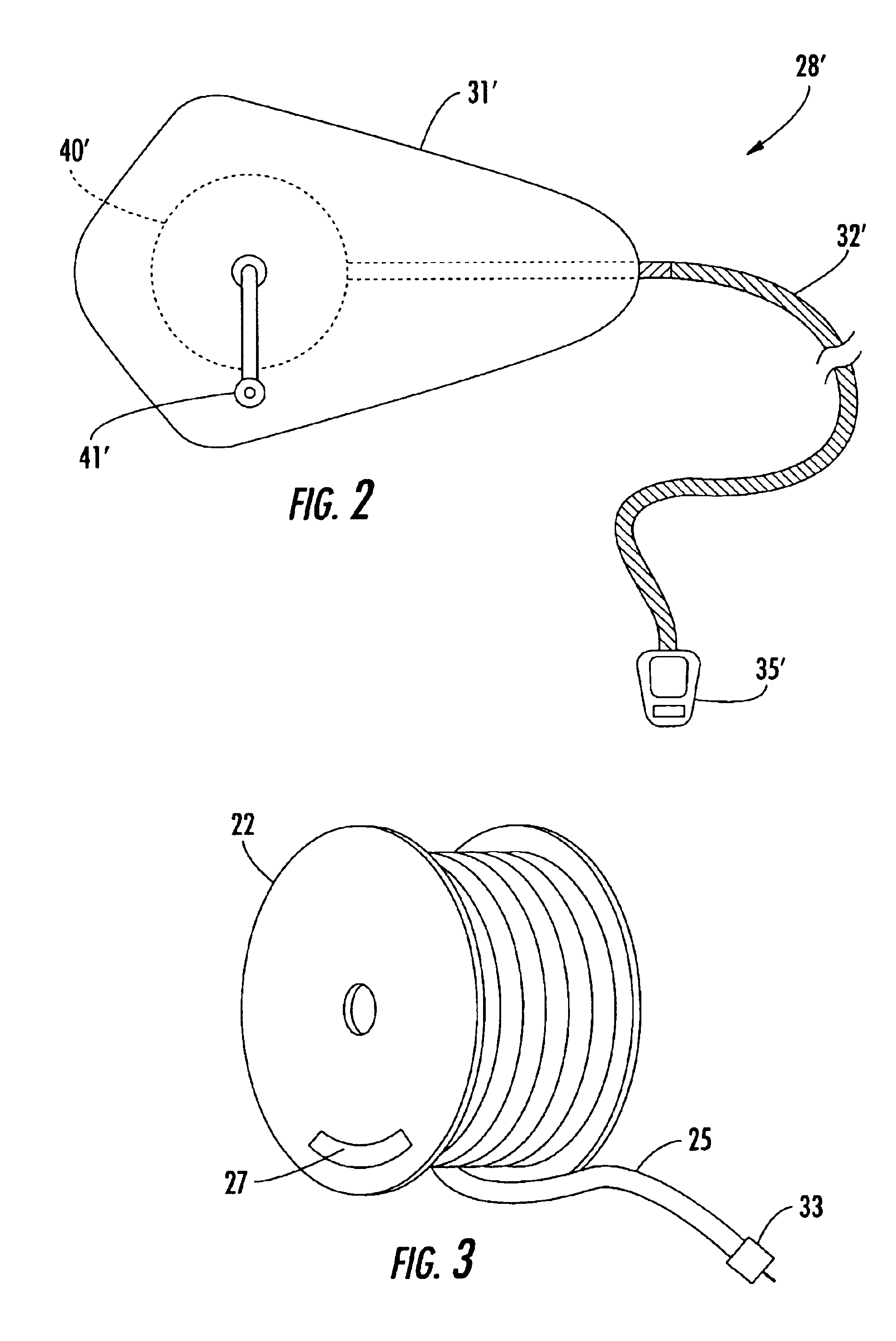
[0023]Referring initially to FIGS. 1 through 3, a cable installation system 20 for use by a cable installer 21 illustratively includes a plurality of cable dispensers 22-24 each having different lengths of cable 25 thereon. The dispensers 22-24 would typically be loaded onto a work truck / van 26 by the installer 21 before coming to an installation site, for exa...


PUM


Abstract

A cable installation system for use by a cable installer may include a plurality of cable dispensers having different lengths of cable. In particular, each cable dispenser may also have a non-numeric, length-identifying marking associated therewith corresponding to the length of cable. Furthermore, the system may also include a cable dispenser indicator device for use by the installer to determine a distance between first and second locations, such as a cable tap and a subscriber interface. The cable dispenser indicator device may also provide an indication to the installer of the non-numeric, length-identifying marking corresponding to the determined distance so that the cable installer can select the corresponding cable dispenser from the plurality thereof. By way of example, the non-numeric, length-identifying markings may include a series of different colors and / or graphics for respective length ranges.

Description

CROSS-REFERENCE TO RELATED APPLICATIONS[0001]This application is a continuation-in-part of co-pending U.S. patent application Ser. No. 10 / 440,995, filed May 19, 2003, which is hereby incorporated herein in its entirety by reference.FIELD OF THE INVENTION[0002]The present invention relates to the field of cable installation, and, more particularly, to systems for use by cable installers to facilitate the installation process and related methods.BACKGROUND OF THE INVENTION[0003]When a user first subscribes to a cable television or phone service, for example, a service provider typically is required to install a cable from a tap to a subscriber interface at the subscriber's house, building, etc. The cable is used to transmit signals between the tap point, which provides access to the service provider's communications network, and the subscriber interface, which is connected to the wires running through the house or building. The type of cable to be installed generally depends upon the ...

Claims


Application Information

Patent Timeline
IPC IPC(8): B65H75/22B65H75/18H02G11/02H02G11/00
CPCB65H75/22H02G11/02B65H2701/32
Inventor ALRUTZ, MARK E.GEMME, CHRISTOPHER P.VOGEL, MARK O.LEE, MARTIN B.
Owner COMMSCOPE INC
Learn More