
Fluid pressure reduction device

a technology of flue gas reduction and pressure reduction device, which is applied in the direction of mechanical equipment, pipe elements, transportation and packaging, etc., can solve the problems of vibration generation of air-borne noise that is annoying to people or may damage the hearing of people, and the failure of pressure retaining components or other types of wear,

Inactive Publication Date: 2005-08-30
FISHER CONTROLS INT LLC
View PDF18 Cites 39 Cited by
  • Summary
  • Abstract
  • Description
  • Claims
  • Application Information

AI Technical Summary

Benefits of technology

[0016]In accordance with certain aspects of the present invention, a method of assembling a fluid pressure reduction device is provided comprising forming a plurality of disks having at least one flow path extending between a hollow center and a perimeter of the disk, each flow path including an inlet section, an outlet section, and an intermediate section extending between the inlet and outlet sections, the flow path dividing the disk into at least first and second blank portions, each disk further including a first bridge portion extending between the first and second blank portions. The disks are stacked along an axis and secured together to form a stacked disk assembly. The first bridge portion of each disk in the stacked disk assembly is then removed.

Problems solved by technology

Pressure and velocity fluctuations are associated with the turbulent fluid motion that act upon the structural elements of the piping system, causing vibration.
Vibration may lead to fatigue failure of pressure retaining components or other types of wear, degradation of performance, or failure of attached instruments.
Even when not physically damaging, vibration generates air-borne noise that is annoying to or may damage the hearing of people.
In industrial applications involving liquids, the chief source of noise, vibration, and damage from the pressure reduction of liquids is cavitation.
The collapsing vapor bubbles may cause noise, vibration, and damage.
In practice, however, such a pressure reduction device is overly difficult and expensive to produce, and therefore fluid pressure reduction devices are known that use multiple stages of pressure reduction.
In reality, however, it has been found that the intermediate right angle turns in the flow passages do not effectively create a restriction for staged pressure reduction.
In addition, the pressure reduction created by the tortuous path is unpredictable since the pressure reduction effected by each right angle turn is not known.
Furthermore, it has been found that the right angle turns may generate pressure and mass flow imbalances and flow inefficiency.
The pressure imbalances may lead to the creation of low pressure areas within the device where the fluid momentarily drops below the vapor pressure and subsequently recovers, thereby creating cavitation and causing damage.
Flow imbalances affect the pressure drop and fluid velocity through the device, wherein a greater mass flows through some passages to result in increased velocity.
As a result, fluid jets exiting the adjacent outlets may collide to form a larger jet flow having greater stream power, thereby increasing the noise level.
The above recited deficiencies and others in currently available trim devices significantly reduce the effectiveness of these devices in providing desired noise attenuation, vibration reduction, and cavitation damage reduction or elimination.

Method used


Image

  • Fluid pressure reduction device
  • Fluid pressure reduction device
  • Fluid pressure reduction device

Examples


Embodiment Construction

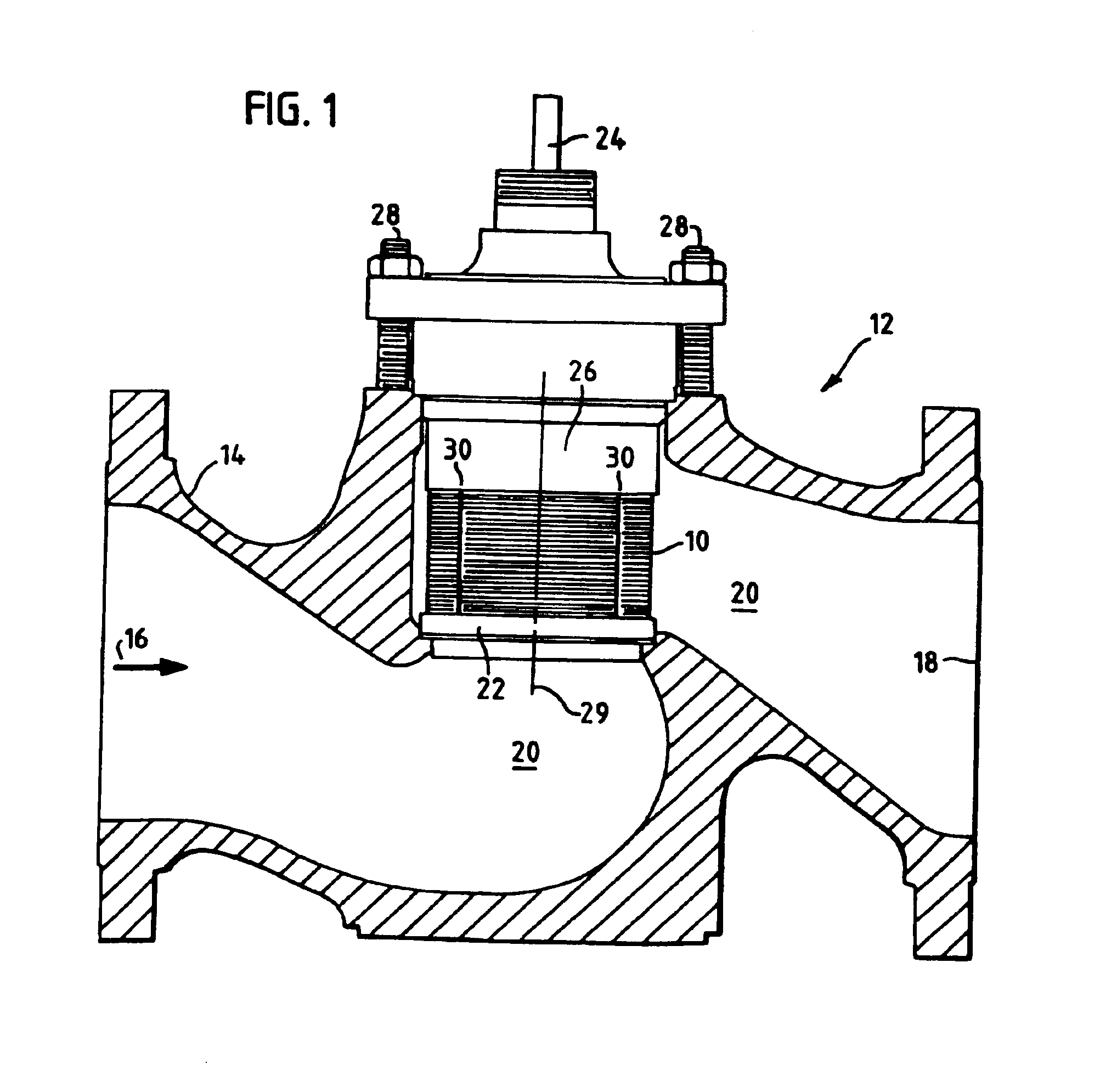
[0030]Referring to FIG. 1, there is illustrated a fluid pressure reduction device in accordance with the principles of the present invention in the form of a valve cage 10 having a plurality of stacked disks and mounted within a fluid control valve 12. The stacked disks are concentric about an axis 29. Fluid control valve 12 includes a valve body 14 having a fluid inlet 16, a fluid outlet 18, and a connecting passageway 20 through the valve body. While the fluid flow from the inlet 16 to the outlet 18 is described herein as proceeding from the left to the right as shown by the arrow in FIG. 1, it will be appreciated that the fluid may flow in the reverse direction (i.e., from the right to the left) without departing from the teachings of the present invention.

[0031]A seat ring 22 is mounted within the valve body passageway 20 and cooperates with a valve operating member 24 to control fluid flow into the interior and through the exterior of the valve cage 10. The valve cage 10 may be...


PUM

PropertyMeasurementUnit
included angleaaaaaaaaaa
angleaaaaaaaaaa
perimeteraaaaaaaaaa

Abstract

A fluid pressure reduction device comprises a plurality of stacked disks having a perimeter and a hollow center aligned along a longitudinal axis. Each disk has at least one flow path extending between the hollow center and the perimeter, the flow path including an inlet section, an outlet section, and an intermediate section extending between the inlet and outlet sections. Each flow path intermediate section includes a pressure reducing structure and a recovery zone positioned immediately downstream of the pressure reducing structure.

Description

CROSS-REFERENCE TO RELATED APPLICATION[0001]This application is a divisional of prior application Ser. No. 09 / 931,484, filed Aug. 16, 2001 now U.S. Pat. No. 6,701,957.FIELD OF THE INVENTION[0002]This invention relates to fluid energy dissipation devices and, more particularly, to a fluid pressure reduction device with low acoustical conversion efficiency for gas flows and also for devices with cavitation avoidance and hence low noise properties for liquid flows.BACKGROUND OF THE INVENTION[0003]In the control of fluid in industrial processes, such as oil and gas pipeline systems, power plants, chemical processes, etc., it is often necessary to reduce the pressure of a fluid. Adjustable flow restriction devices, such as flow control valves and fluid regulators, and other fixed fluid restriction devices, such as diffusers, silencers, and other back pressure devices, are utilized for this task. The purpose of the fluid control valve and / or other fluid restricting device in a given appli...

Claims


Application Information

Patent Timeline
Patent Type & Authority Patents(United States)
IPC IPC(8): F16K47/00F16K47/08F16K47/06F16K1/00F16K47/04
CPCF16K47/04F16K47/08Y10T29/49419Y10T137/86759Y10T137/86734
Inventor MCCARTY, MICHAEL WILDIELONG, TED ALANANDERSON, MICHAEL M.
Owner FISHER CONTROLS INT LLC
Features
  • Generate Ideas
  • Intellectual Property
  • Life Sciences
  • Materials
  • Tech Scout
  • Unparalleled Data Quality
  • Higher Quality Content
  • 60% Fewer Hallucinations
Learn More