
Cap for a container

a container and cap technology, applied in the field of caps, can solve the problems of inconvenient arrangement, liquid in the carafe will leak out through the open valve, and the position of the valve can be accidentally changed, so as to reduce the probability of opening

Inactive Publication Date: 2005-08-30
TRUDEAU 1889
View PDF30 Cites 55 Cited by
  • Summary
  • Abstract
  • Description
  • Claims
  • Application Information

AI Technical Summary

Benefits of technology

[0006]The present invention recognizes that selective control of the state (e.g., open or closed) of a valve should be associated with movement of an actuator in a different direction than for securing the valve in the open position. If the combination of movements required to lock the valve in the open position can be made sufficiently complex to reduce its probability of opening unintentionally, the cap of the present invention will be rendered more likely to prevent accidental discharge than a cap that requires mere rotation or translation to maintain its passageway open. Meanwhile, the combination of movements should be simple enough to be performed by a single finger.
[0010]The multi-directional movement includes movement of the actuator in a first direction whereby the valve is caused to move from the closed position to the open position, as well as movement of the actuator in a second direction after the actuator has moved at least partly in the first direction. The two movements need not occur sequentially. In fact, an embodiment of the invention provides that both movement of the actuator in the first direction and movement of the actuator in the second direction may occur at the same time, allowing gradual opening of the valve, which is eventually locked when fully opened.

Problems solved by technology

Clearly, such arrangements are inconvenient, as the user is required to continuously maintain pressure on the region during the pouring process in order to prevent the valve from returning to its closed position.
However, a main inconvenience with such types of containers is that the position of the valve can accidentally be changed from, say, the open position to the closed position.
If this accidental change of valve state occurs as the carafe falls during transportation, the liquid in the carafe will leak out through the open valve.

Method used


Image

  • Cap for a container
  • Cap for a container
  • Cap for a container

Examples


Embodiment Construction

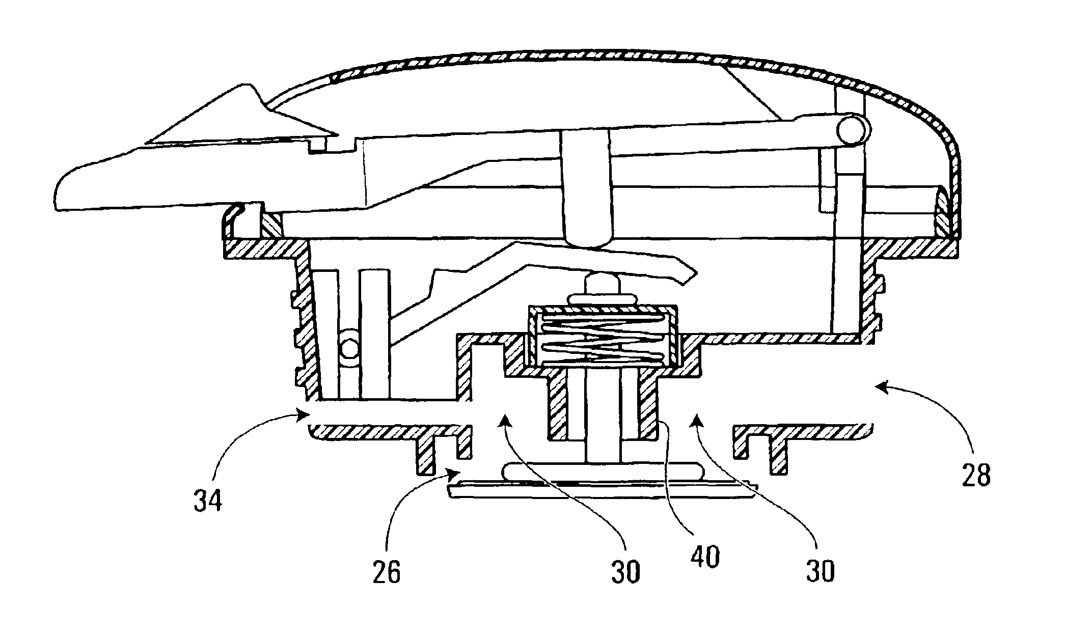
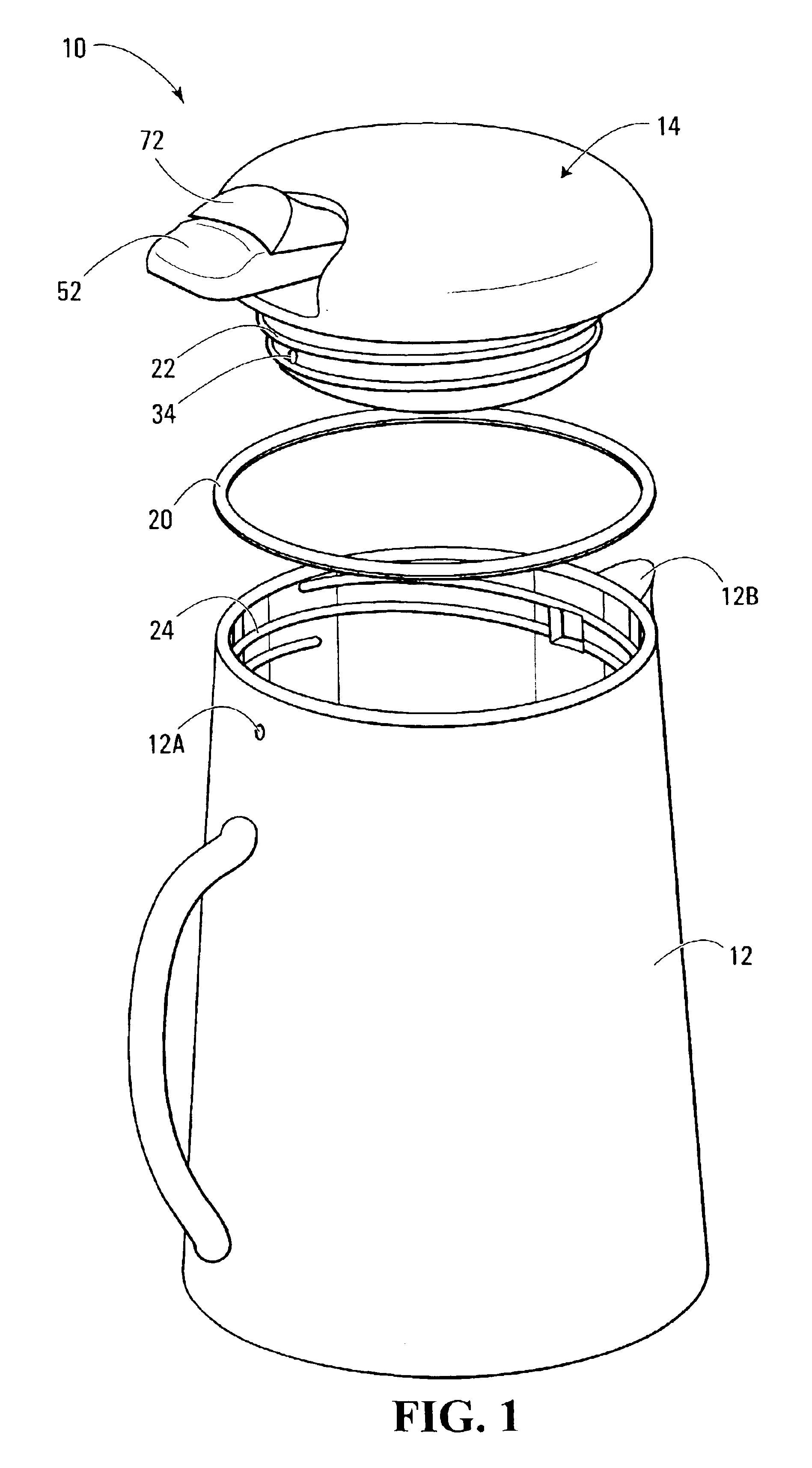
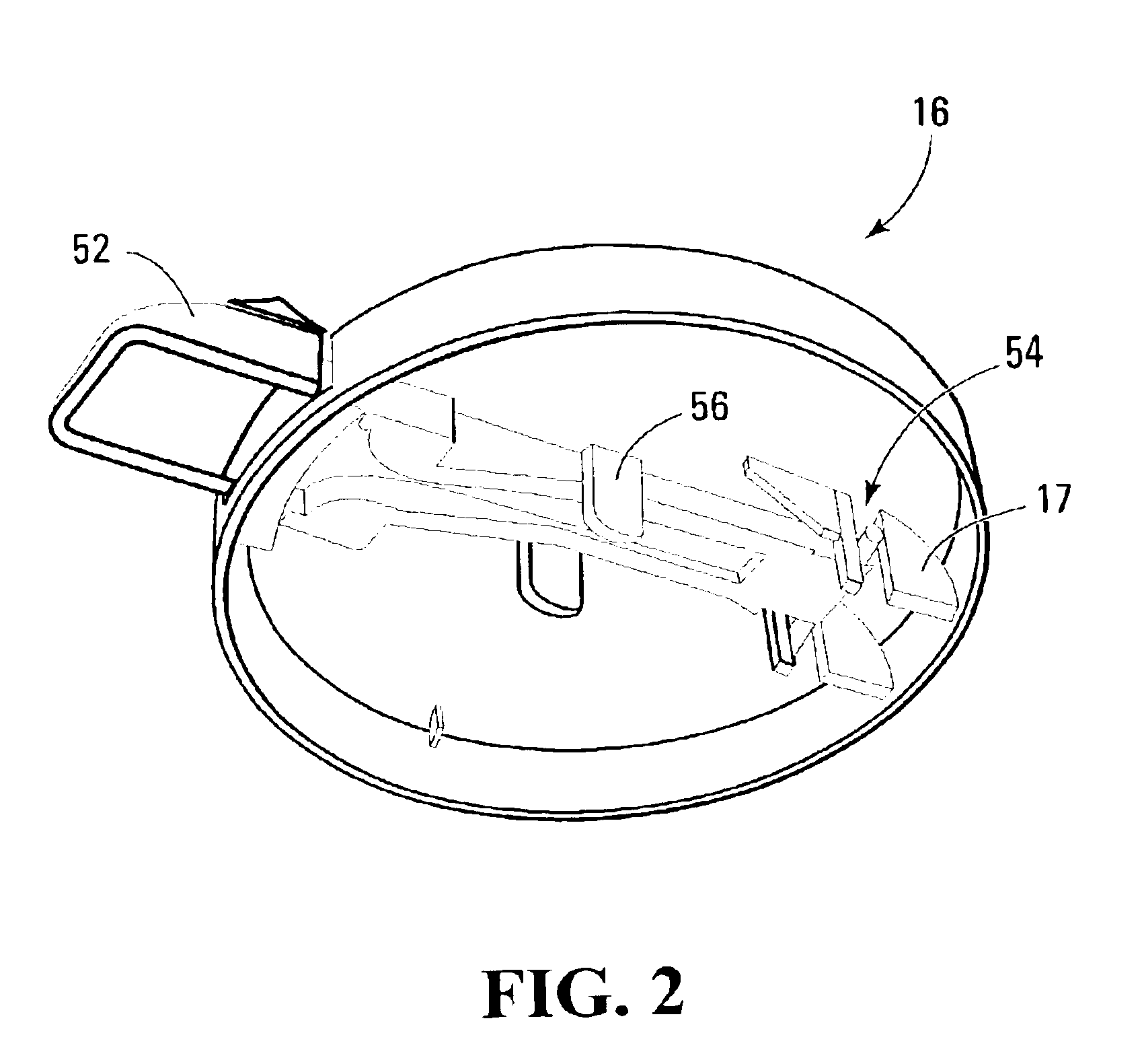
[0024]With reference to FIGS. 1 to 4B, there is shown a cap 10 for a container 12 adapted to carry a liquid such as coffee, water or juice, among others. The cap 10 includes a body 14 which may be formed from a cover portion 16 and a base portion 18 as shown particularly well in FIGS. 2, 4A and 4B. Each of the cover portion 16 and the base portion 18 includes components that will be described in greater detail later on. The cover portion 16 and the base portion 18 may be manufactured and assembled separately. The cover portion 16 and the base portion 18 include mating peripheral portions made of plastic which are resilient yet sufficiently flexible to allow complementary components 17, 19 on the cover portion and the base portion to mate in snap-in fashion. It may be advantageous to make the body 14, once assembled, impossible to separate into its constituent cover and base portions 16, 18 without breaking either one. In other embodiments, it may be advantageous to allow the complem...


PUM

PropertyMeasurementUnit
movementaaaaaaaaaa
pressureaaaaaaaaaa
angleaaaaaaaaaa

Abstract

Cap for a container, including a body having an inlet, a spout and a passageway therebetween. The cap also includes a valve movable between a first position wherein the passageway is blocked and a second position wherein the passageway is at least partly unblocked, the valve being biased towards the first position. Furthermore, the cap includes an actuator mounted to the body and engaging the valve. Selective control of the state of the valve is associated with movement of the actuator in a different direction than for securing the valve in the open position. The combination of movements required to lock the valve in the open position is sufficiently complex to reduce its probability of opening unintentionally. Meanwhile, the combination of movements is simple enough to be performed by a single finger.

Description

FIELD OF THE INVENTION[0001]The present invention relates generally to a cap for a container and, in particular, to a cap for a container adapted to carry a liquid suitable for human consumption.BACKGROUND OF THE INVENTION[0002]Portable beverage containers of the carafe type typically consist of a cylindrical vessel to which is affixed a cap, such as a screw cap. The cap is removable so that it, as well as the interior of the beverage container, can be washed. The cap includes an opening through which the liquid is poured from the beverage container into a glass or mug. A mechanism is usually provided for selectively blocking or liberating the opening so that the liquid from the inside of the body may pass therethrough.[0003]Certain mechanisms for allowing the beverage to be released through the opening of a container include spring-loaded valves which are actuated by the user of the carafe in order to expose the opening. Such mechanisms frequently rely on depression of a region of ...

Claims


Application Information

Patent Timeline
Patent Type & Authority Patents(United States)
IPC IPC(8): A47J41/00
CPCA47J41/0027
Inventor TARDIF, PIERRE
Owner TRUDEAU 1889
Learn More