Method and apparatus for aligning an X-ray source and detector at various source to image distances

a detector and x-ray technology, applied in the field of digital imaging systems, can solve the problems of inaccurate placement or cropping of the patient's field of view, complex installation and setup procedure of typical prior art digital imaging systems, such as digital radiographic imaging systems, and achieve the effect of preventing cropping or misalignmen

Inactive Publication Date: 2005-08-30
GE MEDICAL SYST GLOBAL TECH CO LLC
View PDF1 Cites 29 Cited by
  • Summary
  • Abstract
  • Description
  • Claims
  • Application Information

AI Technical Summary

Benefits of technology

[0008]The present invention addresses one or more of the shortcomings noted above. For example, a method for calibrating the alignment of a source to a detector in a medical imaging system to account for variations due to mechanical or physical misalignments in the system includes initially determining a home position for each of the source and the detector at a known source to image distance. Thereafter, the source is moved to a second source to image distance. At the second source to image distance, and offset is calculated between an expected location of the source and an actual location of the source. During operation of the medical imaging system, the source is moved by a distance equivalent to the offset, wherein the source and detector are aligned. In another aspect, a method for calibrating the position of a digital radiographic imaging system is provided. In this method, a home position at a first known source to image distance is initially calibrated. The source to image distance is then changed, the source is directed at the detector, the source is moved to an aligned position wherein the source is aligned with the detector. An offset is calculated as a function of the aligned position. The offset is stored, and the procedure is repeated at a number of offset locations, wherein a map of offsets is developed. During real time operation, these offsets can be used to align the source and detector to prevent cropping or misalignment.

Problems solved by technology

The installation and setup procedure for typical prior art digital imaging systems, such as digital radiographic imaging systems, are both complex and time-consuming.
While each of these method of calibration are perfectly acceptable if the mechanical linkages and the mounting locations are straight, there are often irregularities in each.
Therefore, when either the X-ray source or detector is moved even in what appears to be a straight line, the source can become misaligned with the detector, resulting in an image in which the field of view is not appropriately positioned on the patient.
In this case, the resultant images can be inaccurately placed or cropped, such that the portion of the anatomy sought to be imaged can be lost.

Method used


Image

  • Method and apparatus for aligning an X-ray source and detector at various source to image distances
  • Method and apparatus for aligning an X-ray source and detector at various source to image distances
  • Method and apparatus for aligning an X-ray source and detector at various source to image distances

Examples


Embodiment Construction

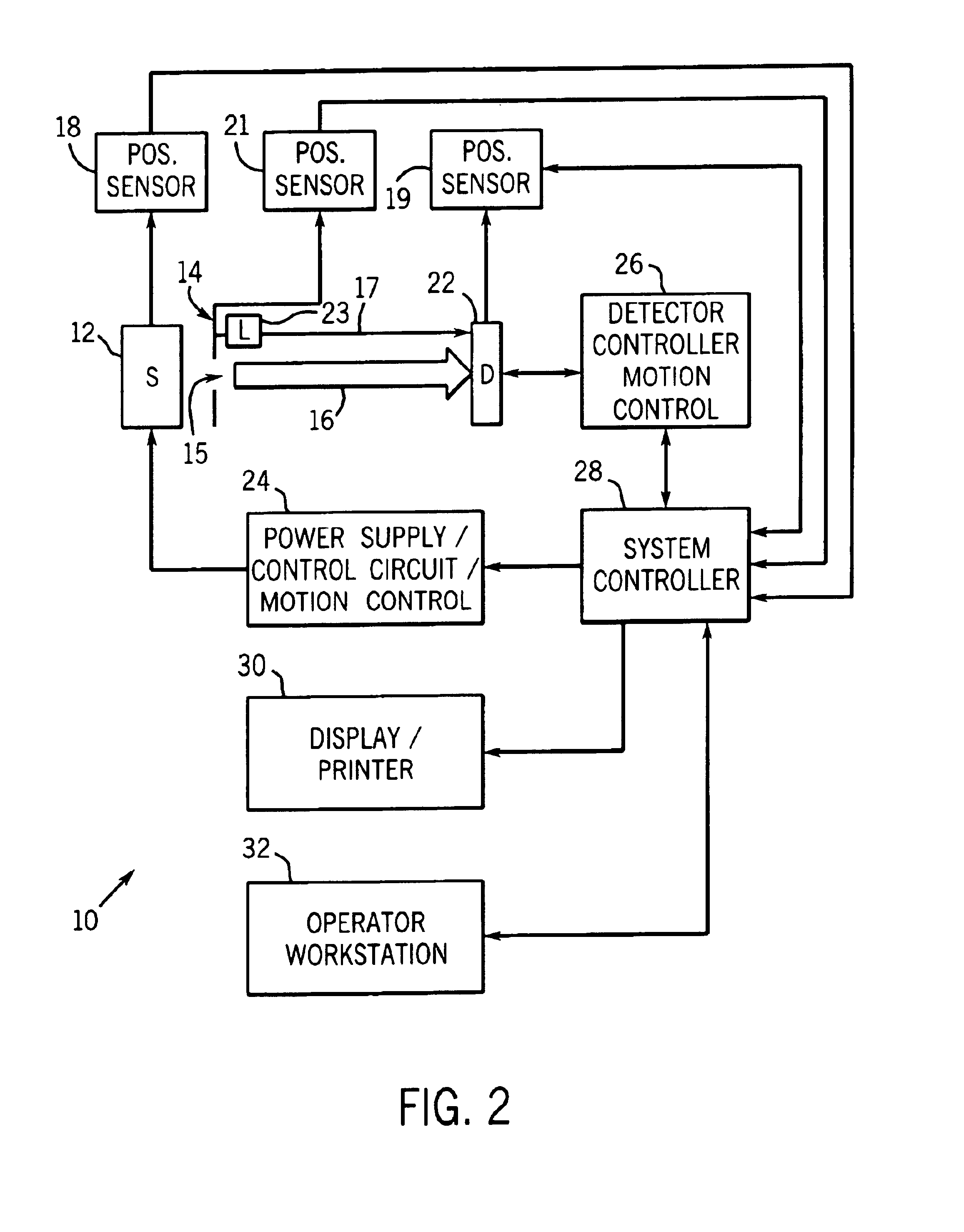
[0015]The following detailed description is made with reference to a digital radiographic imaging system having an x-ray source and a digital detector configured to detect x-ray beams generated by the source. It should be understood, however, that the system and method described hereafter can be implemented in other types of digital imaging systems which have a source that generates radiation other than in the x-ray spectrum (e.g., visible light, infrared, etc.). In such imaging systems, an appropriate digital detector is provided which is configured to detect the particular type of radiation generated by the radiation source.

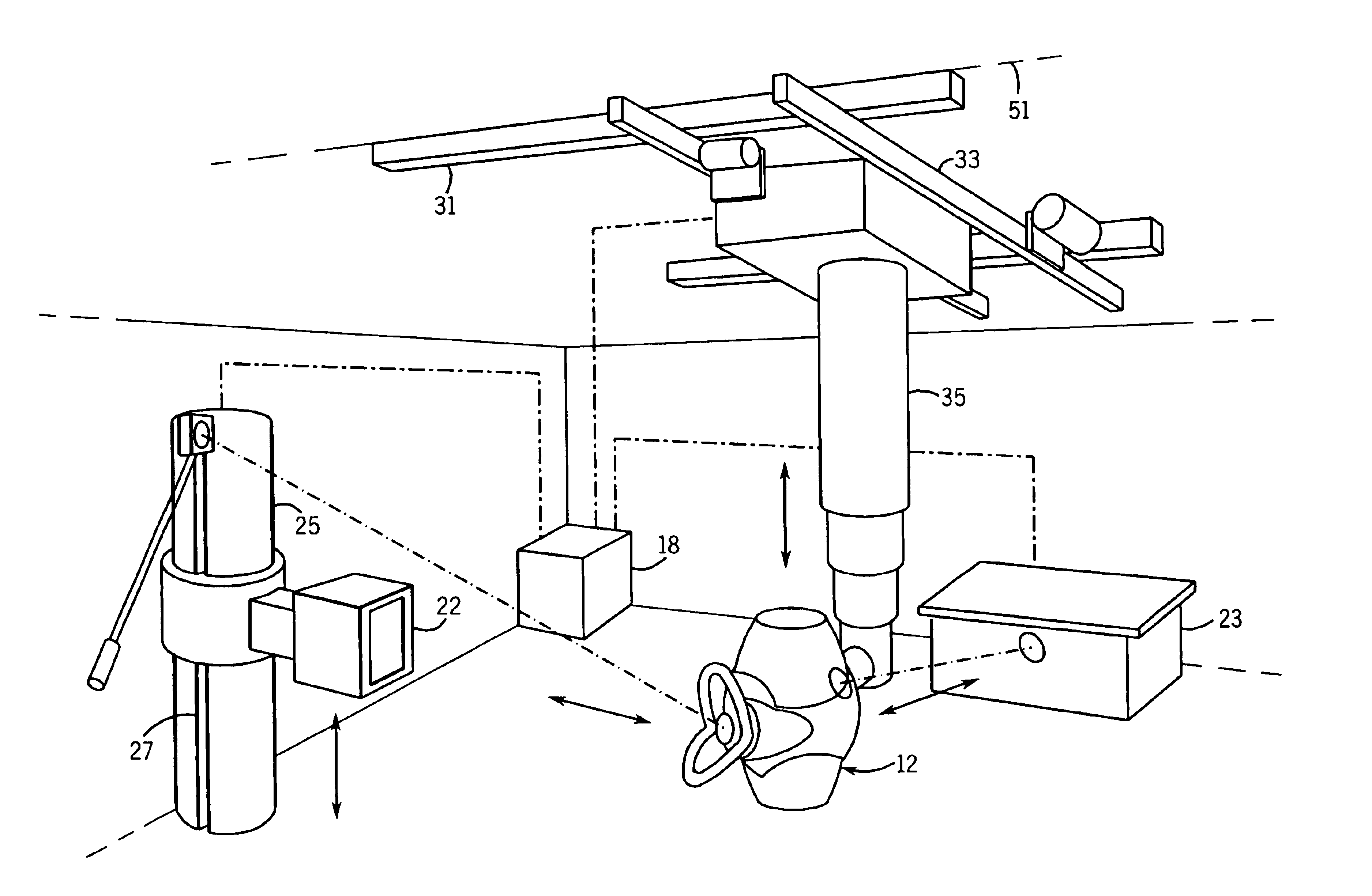
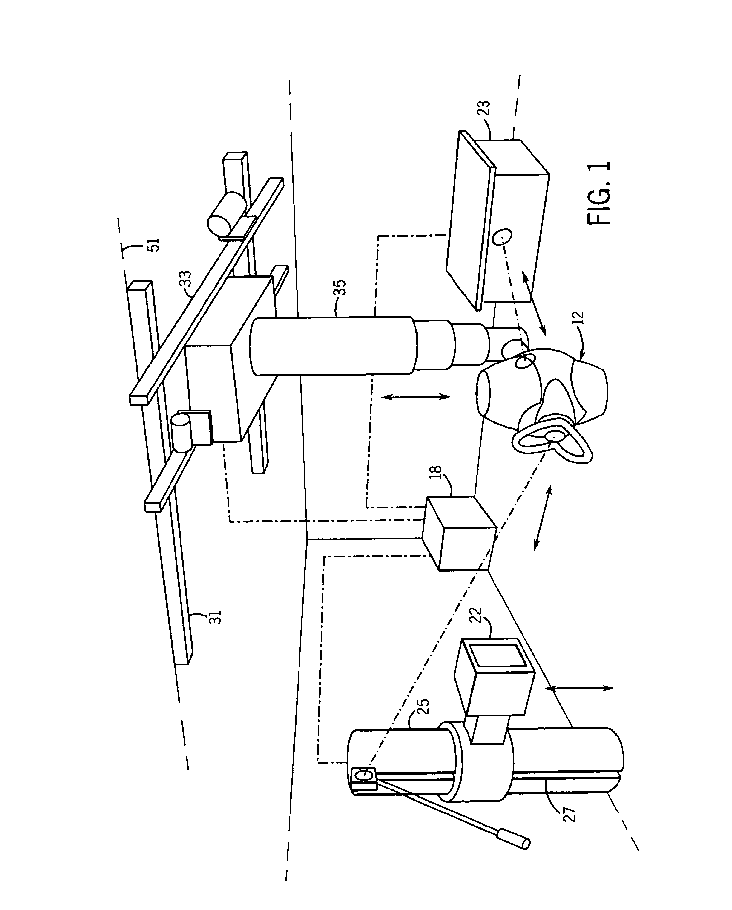
[0016]Turning now to the figures and more particularly to FIGS. 1 and 2, a perspective view and a diagrammatical view of an imaging system 10 for acquiring and processing discrete pixel image data is shown. In the illustrated embodiments, system 10 is a digital x-ray system that facilitates installation and calibration procedures such that accurate image data c...


PUM


Abstract

A digital radiographic imaging system includes an offset table for determining mechanical and structural offsets which would, if not corrected, misalign the source and detector during use. The method can correct for inaccuracies in mechanical linkages, examination rooms and other mounting structures, and “drift” induced during use of the system.

Description

FIELD OF THE INVENTION[0001]The present invention relates generally to digital imaging systems and, more particularly, to a system and setup procedure for determining an offset for centering a radiation source with respect to a digital detector in a digital imaging system, irrespective of variations in the dimensions of the examination room, mounting structure, or mechanical linkages.BACKGROUND OF THE INVENTION[0002]X-Ray systems, such as digital radiographic imaging systems, comprise an x-ray tube or source and a detector. The source is moveably mounted to a mounting structure such as a wall or ceiling in an examination room, and the detector is provided on a horizontal table or vertical stand. Typically, the detector mounting structures are also moveable in at least one direction.[0003]In a typical setup, the source is mounted to a rail provided on the ceiling the X-ray room, and the detector or digital wall stand is provided on a stand positioned against a wall of the room. The s...

Claims


Application Information

Patent Timeline
Patent Type & Authority Patents(United States)
IPC IPC(8): A61B6/00A61B6/08
CPCA61B6/08A61B6/4464A61B6/547A61B6/587A61B6/4452
Inventor ZHANG, JOHN JUNNI, XIANFENGSTEPANOVICH, ERIC NICHOLASUPPALURI, RENUKABOEHM, MANFRED DAVID
Owner GE MEDICAL SYST GLOBAL TECH CO LLC
Why Eureka
Try Eureka