Portable power generating devices

a power generation device and portability technology, applied in the direction of liquid fuel engines, marine propulsion, vessels, etc., can solve the problems of high construction costs, many negative consequences of permanent structures, and high construction costs of permanent structures, etc., and achieve the effect of simple method and low cos

Inactive Publication Date: 2005-08-30
NATURAL FORCES
View PDF10 Cites 31 Cited by
  • Summary
  • Abstract
  • Description
  • Claims
  • Application Information

AI Technical Summary

Benefits of technology

[0014]Yet another aspect of this invention there is provided portable power generating devices for converting blowing air or air current to useful, mechanical and / or electrical energy. In another aspect of this invention there is provided an inexpensive and simplistic method for converting potential energy in blowing air or air current to useful mechanical and / or electrical energy.

Problems solved by technology

A shortcoming of many existing hydropower or hydroelectric (hereinafter individually and collectively referred to as “hydropower”) systems are the costs associated with constructing these massive structures.
These permanent structures have numerous negative consequences.
Permanent structures are very expensive to construct and maintain and the costs associated with decommissioning these permanent structures are very high.
Moreover, these permanent structures seriously alter the hydrology of impounded waterways creating flood hazards and safety concerns to surrounding areas.
In Oregon, Washington, and Idaho, a multi-million dollar salmon fishery was destroyed resulting in unemployment for thousands of people.
Environmentalists have protested against these permanent structures because of their impact to the environment.

Method used


Image

  • Portable power generating devices
  • Portable power generating devices
  • Portable power generating devices

Examples


Embodiment Construction

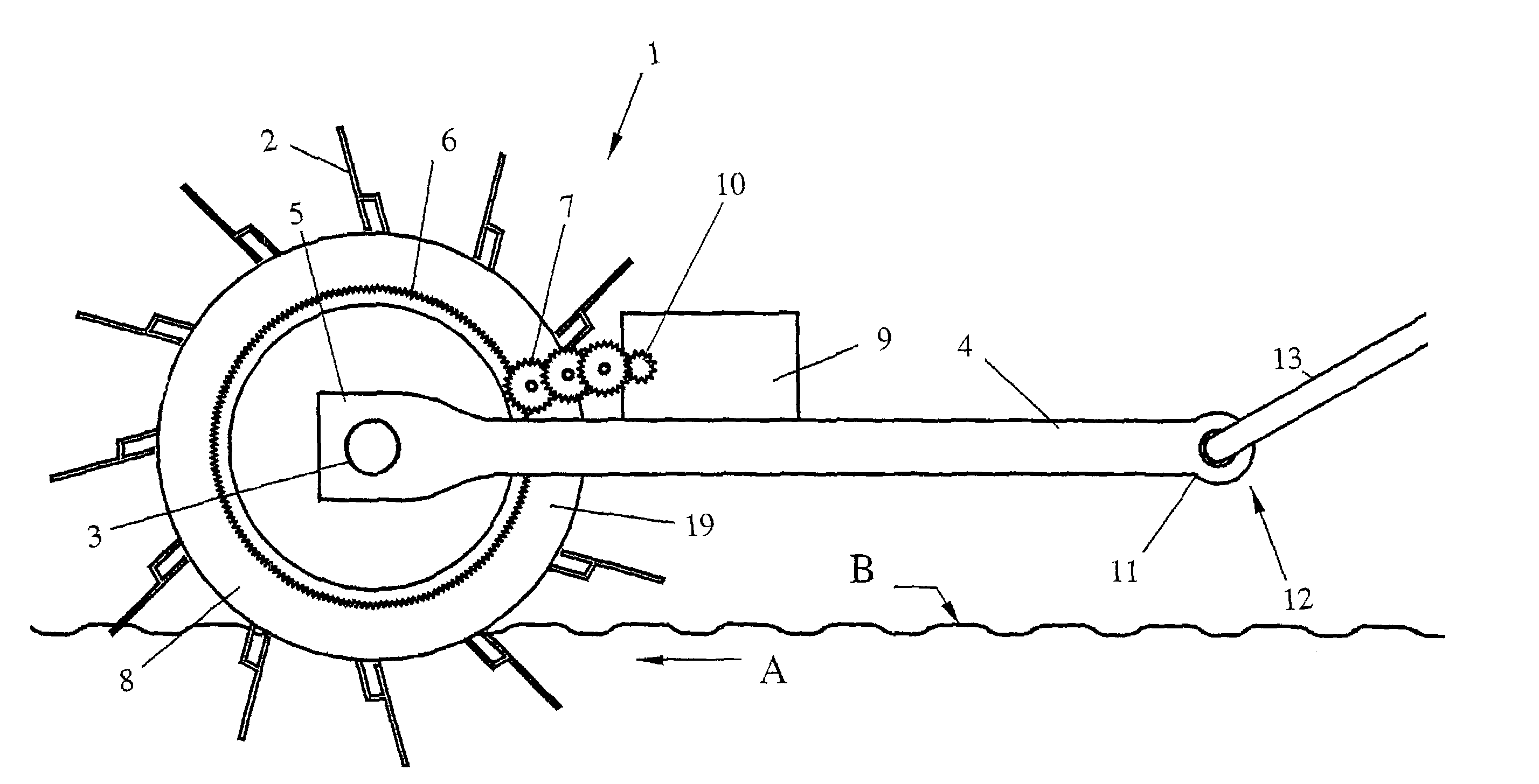
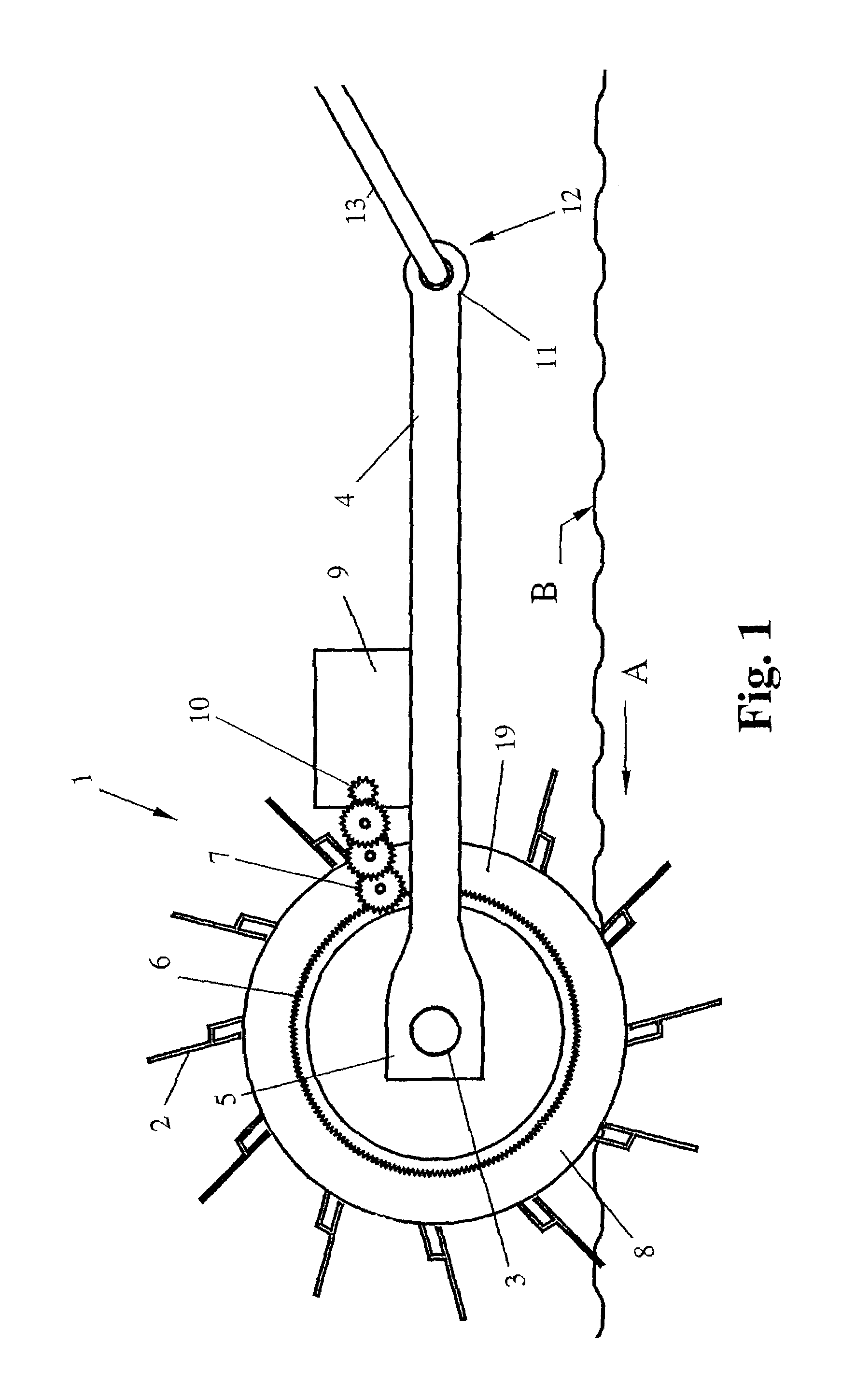
[0030]FIG. 1 illustrates a single drum portable power generating device, generally designated 1. The portable power generating device 1 is for use in conjunction with a moving fluid, such as water. Arrow “B” shows a surface of the moving fluid and arrow “A” shows which direction the fluid is moving in. The single drum portable power generating device 1 has a single drum 19, which is cylindrical and has buoyancy. The single drum portable power generating device 1 has vanes 2 operatively mounted around the outer circumference thereon. The vanes 2 extend outwardly from the outer circumference of the single drum 19 of the single drum portable power generating device 1. In all embodiments discussed hereinafter, the vanes can be of various configurations and designs such as straight, curved, angled, cupped, ribbed, concave, rigid, flexible, steel, plastic or any other similar structure. The configuration and design of the vanes 2 are dependent upon many factors, such as, obtaining the max...


PUM


Abstract

Portable power generating devices are provided for converting potential energy from flowing water, water current, blowing air or air current to mechanical and/or electrical energy. The potential energy is converted to a rotational movement, and the rotational energy is communicated to power conversion units for conversion, wherein the rotational movement is converted to mechanical, electrical or some other useable or useful energy.

Description

CROSS REFERENCE TO RELATED APPLICATIONS[0001]This application claims priority of prior Provisional Application No. 60 / 382,247 filed in the United States of America on May 21, 2002.TECHNICAL FIELD OF THE INVENTION[0002]The invention relates to portable power generating devices and more particularly to portable devices for converting potential energy from flowing water, water current, blowing air or air current to mechanical and / or electrical energy.DESCRIPTION OF THE RELATED ART[0003]Hydropower energy is the mechanical and / or electrical energy converted from potential energy in moving water or water current. Hydroelectric power is the electrical power converted from the potential energy in, among other things, moving water or water current. It is important to note that a mechanical function is usually required to convert potential energy in moving water or water current to hydroelectric power.[0004]A shortcoming of many existing hydropower or hydroelectric (hereinafter individually a...

Claims


Application Information

Patent Timeline
Patent Type & Authority Patents(United States)
IPC IPC(8): F01D1/00F03B7/00F03B17/06
CPCF03B13/1805F03B13/22F03B17/061F03B17/063F05B2210/16Y02E10/28Y10S415/908Y02E10/38Y02E10/30Y02E10/20
Inventor PLATT, MICHAEL D.PLATT, ERIC E.
Owner NATURAL FORCES
Why Eureka
Try Eureka