Elastomeric force module for orthodontic treatment

a force module and orthodontic technology, applied in the field of elastomeric devices, can solve the problems of long treatment time, unsatisfactory headgear, and embarrassment, and achieve the effects of avoiding concentrated stresses in certain areas, preventing material degradation, and reducing the number of patients

Inactive Publication Date: 2005-08-30
3M INNOVATIVE PROPERTIES CO
View PDF20 Cites 27 Cited by
  • Summary
  • Abstract
  • Description
  • Claims
  • Application Information

AI Technical Summary

Benefits of technology

[0018]The present invention is directed toward an improved orthodontic force module having a shape that provides more uniform stress along its length during use. As a result, premature degradation of the material and breakage that might otherwise be due to high, concentrated stresses in certain areas are avoided. The force module of the present invention may be elongated to a relatively large extent without rupturing.
[0019]The orthodontic force module of the present invention provides a number of important advantages. For one thing, a force module that is less likely to break during the course of treatment helps reduce the likelihood that the overall treatment time will be extended since the desired corrective forces are continuously provided without interruption. Additionally, the relatively low stresses encountered by the force module of the present invention during use helps to increase the length of time that the module may be used before replacement is needed. The principles of the present invention may be used for the construction of any orthodontic force module, regardless of the composition of the elastomeric material.

Problems solved by technology

However, headgear is often considered unsatisfactory because it is visibly apparent.
Headgear may serve as a source of embarrassment, particularly among adolescent patients who may experience teasing from classmates.
Unfortunately, such practice may lengthen treatment time since the desired corrective forces are applied during only a portion of each calendar day.
To date, however, few orthodontic force modules with alternative materials are available.

Method used


Image

  • Elastomeric force module for orthodontic treatment
  • Elastomeric force module for orthodontic treatment
  • Elastomeric force module for orthodontic treatment

Examples


Embodiment Construction

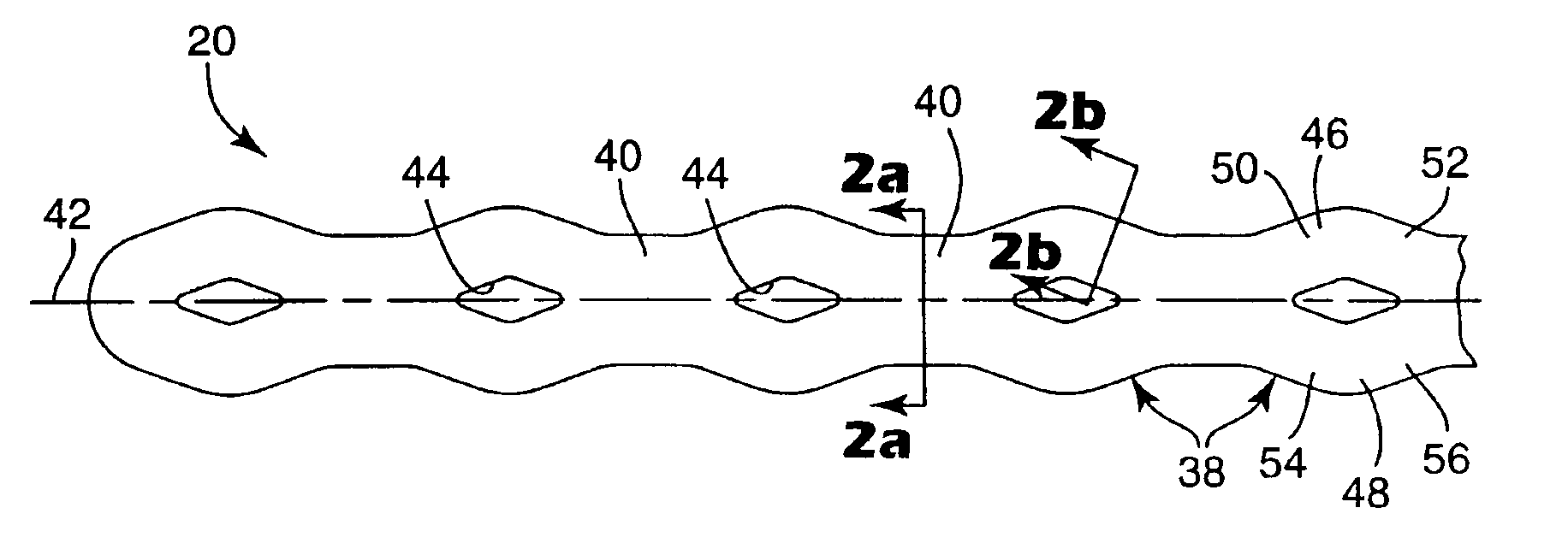
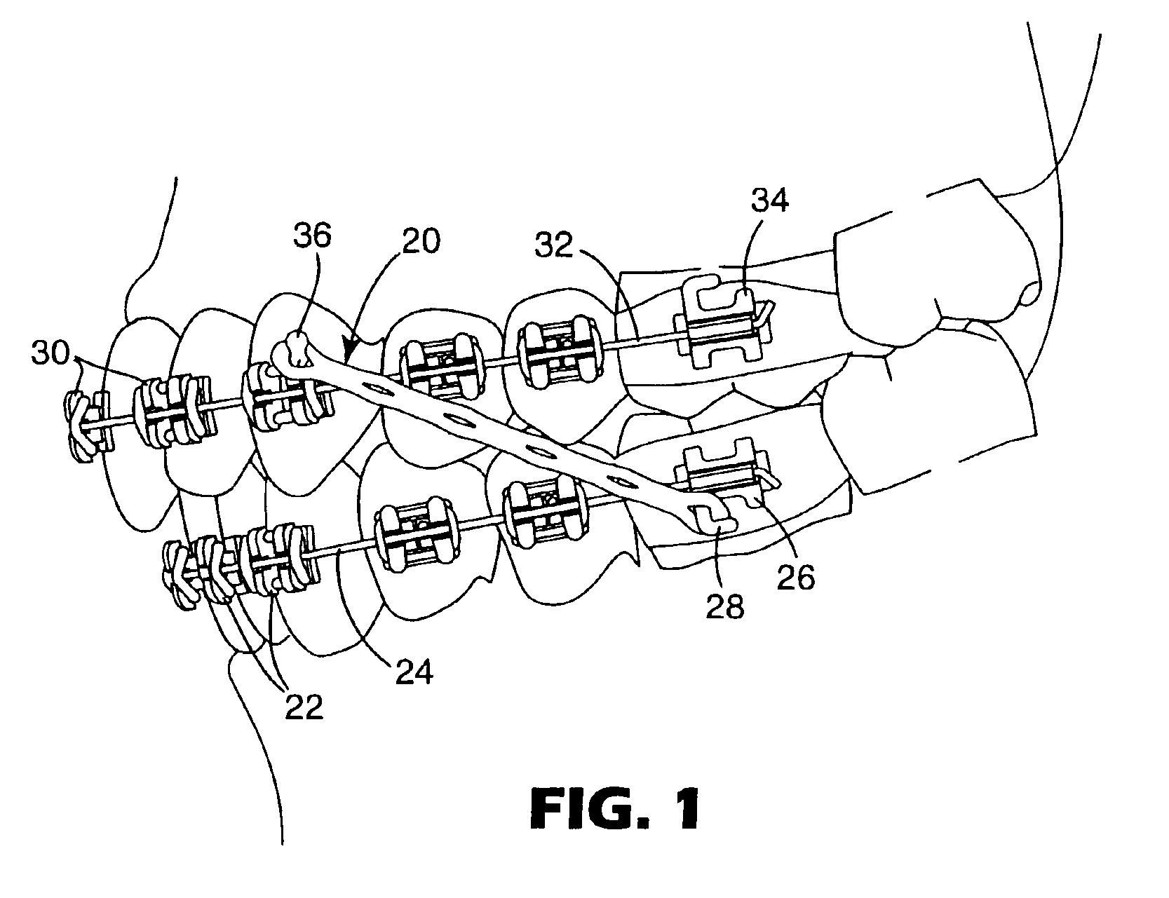
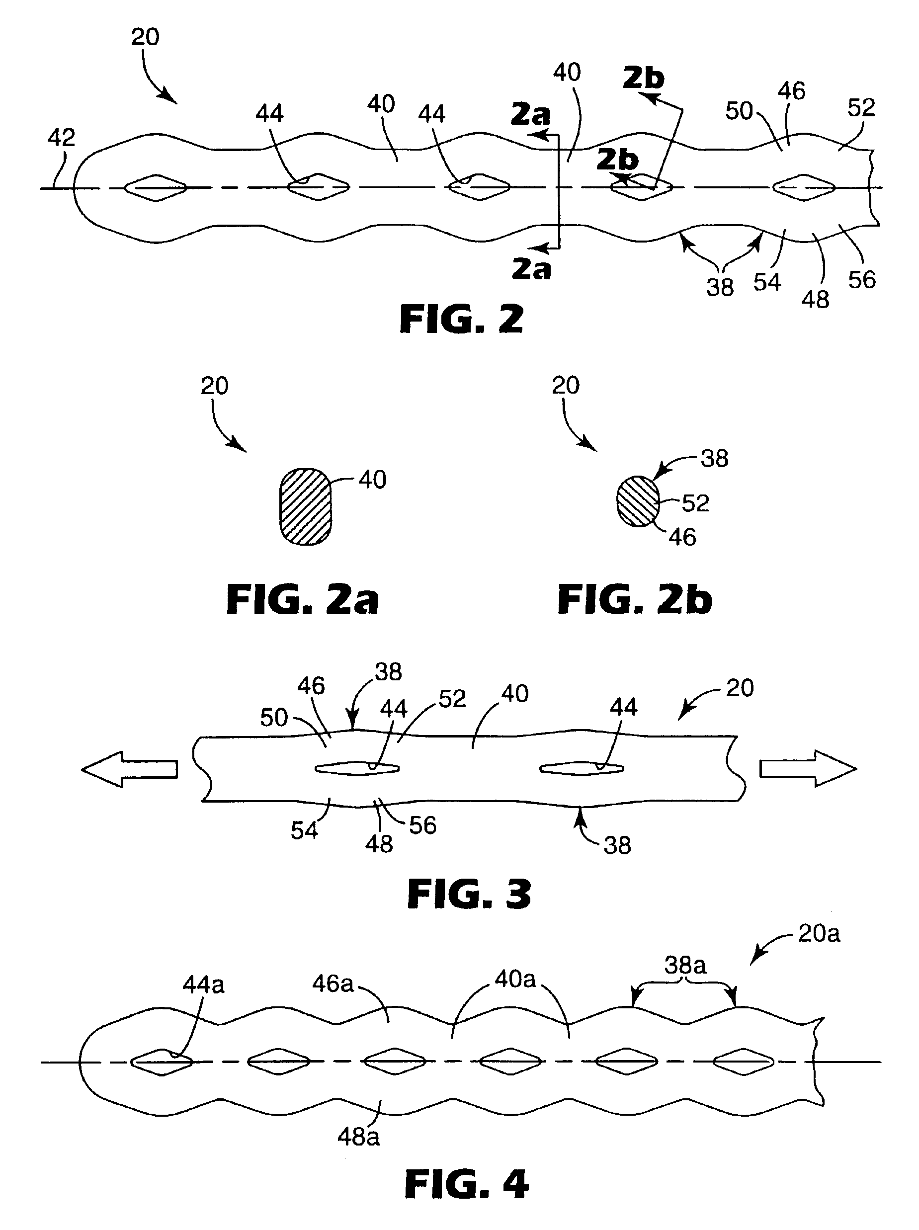
[0040]FIG. 1 is an illustration showing an exemplary use of an orthodontic force module 20 that is constructed according to one embodiment of the present invention. The force module 20 is installed in the oral cavity of an orthodontic patient undergoing treatment. The force module 20 in this example is arranged to correct a Class II malocclusion by urging the patient's lower dental arch in a forward direction relative to the patient's upper dental arch.

[0041]In more detail, a set of lower dental brackets 22 is secured to corresponding teeth of the patient's lower dental arch and an archwire 24 is placed in the slots of the brackets 22. Ends of the archwire 24 are received in buccal tubes 26 (only one shown) that are mounted on the patient's lower molar teeth. Each of the lower buccal tubes 26 has a hook 28 that extends in a distal direction (i.e., in a direction away from the middle of the patient's dental arch).

[0042]Similarly, a set of upper orthodontic brackets 30 is secured to t...


PUM


Abstract

An orthodontic force module is made of an elastomeric material and includes one or more eyelet segments along with one or more connector segments coupled to the eyelet segments. The configuration of the eyelet segments and the connector segments is arranged so that a substantially constant cross-sectional area is provided throughout the working length of the force module. As a result, the resistance to elongation is substantially uniform throughout the working range of the force module and premature degradation and failure due to relatively high, concentrated stresses are avoided.

Description

BACKGROUND OF THE INVENTION[0001]1. Field of the Invention[0002]This invention relates to an elastomeric device that is used in the oral cavity during orthodontic treatment. More particularly, the present invention is directed to an elastomeric orthodontic force module that is useful for moving one or more teeth to desired locations along a dental arch, or for moving one dental arch relative to the other.[0003]2. Description of the Related Art[0004]Orthodontia is a specialized field within the general subject area of dentistry. Orthodontic treatment involves movement of malpositioned teeth to correct locations along the dental arch. In some instances, orthodontic treatment also includes movement of one dental arch as a unit relative to the other dental arch. Orthodontic treatment can result in improved occlusion as well as a more pleasing aesthetic appearance.[0005]One type of orthodontic treatment involves the use of a set of components that are collectively known as “braces”. In t...

Claims


Application Information

Patent Timeline
Patent Type & Authority Patents(United States)
IPC IPC(8): A61C7/00A61C7/30A61C7/36
CPCA61C7/303A61C7/36
Inventor CLEARY, JAMES D.
Owner 3M INNOVATIVE PROPERTIES CO
Why Eureka
Try Eureka