Millimeter wave imaging system

a technology of imaging system and millimeter wave, applied in the field of millimeter wave imaging system, can solve the problems of complex and costly construction of the system referred to abov

Inactive Publication Date: 2005-08-30
TREX ENTERPRISE
View PDF5 Cites 78 Cited by
  • Summary
  • Abstract
  • Description
  • Claims
  • Application Information

AI Technical Summary

Problems solved by technology

The systems referred to above are complicated and costly to construct.

Method used


Image

  • Millimeter wave imaging system
  • Millimeter wave imaging system
  • Millimeter wave imaging system

Examples


Embodiment Construction

Antenna Element

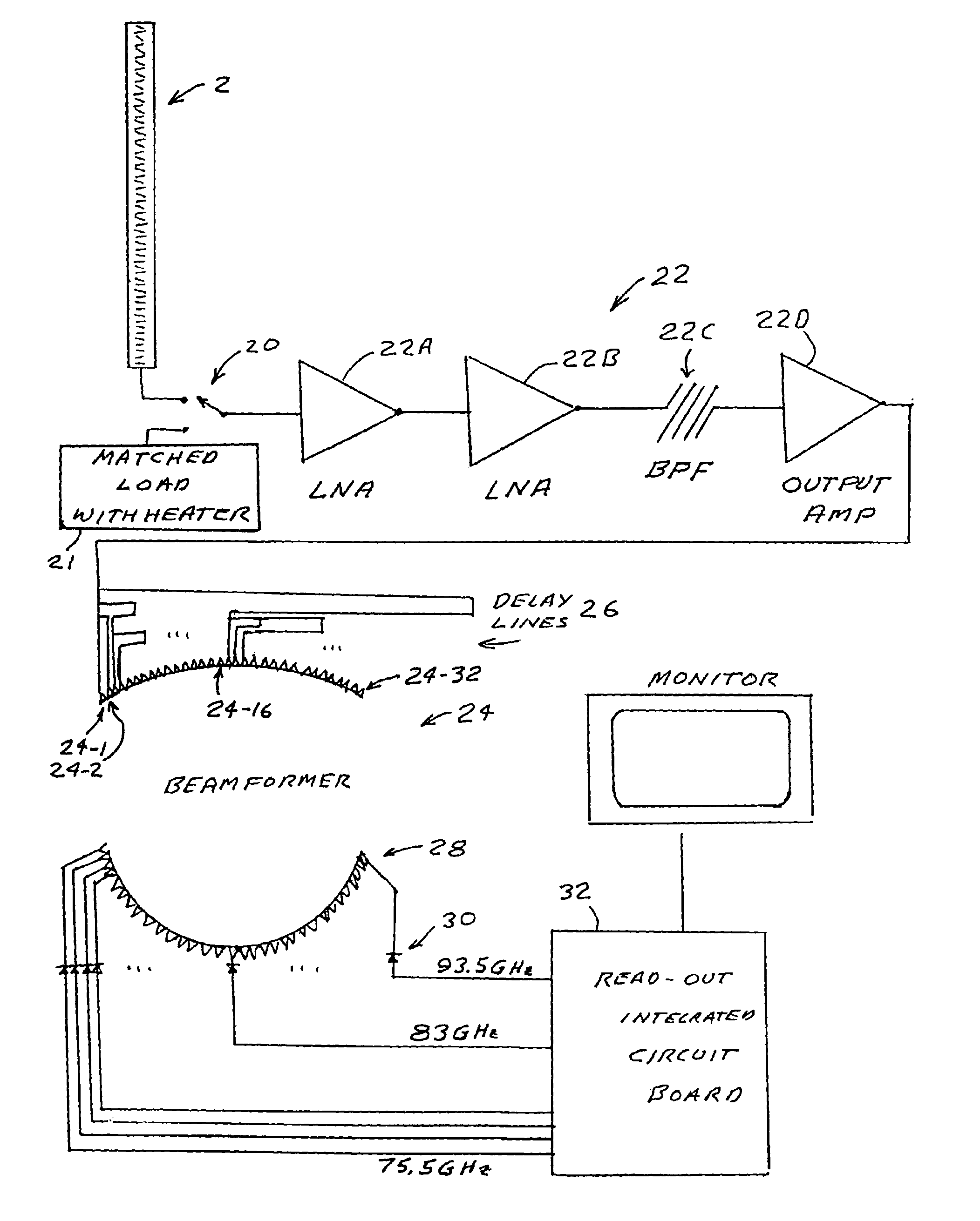
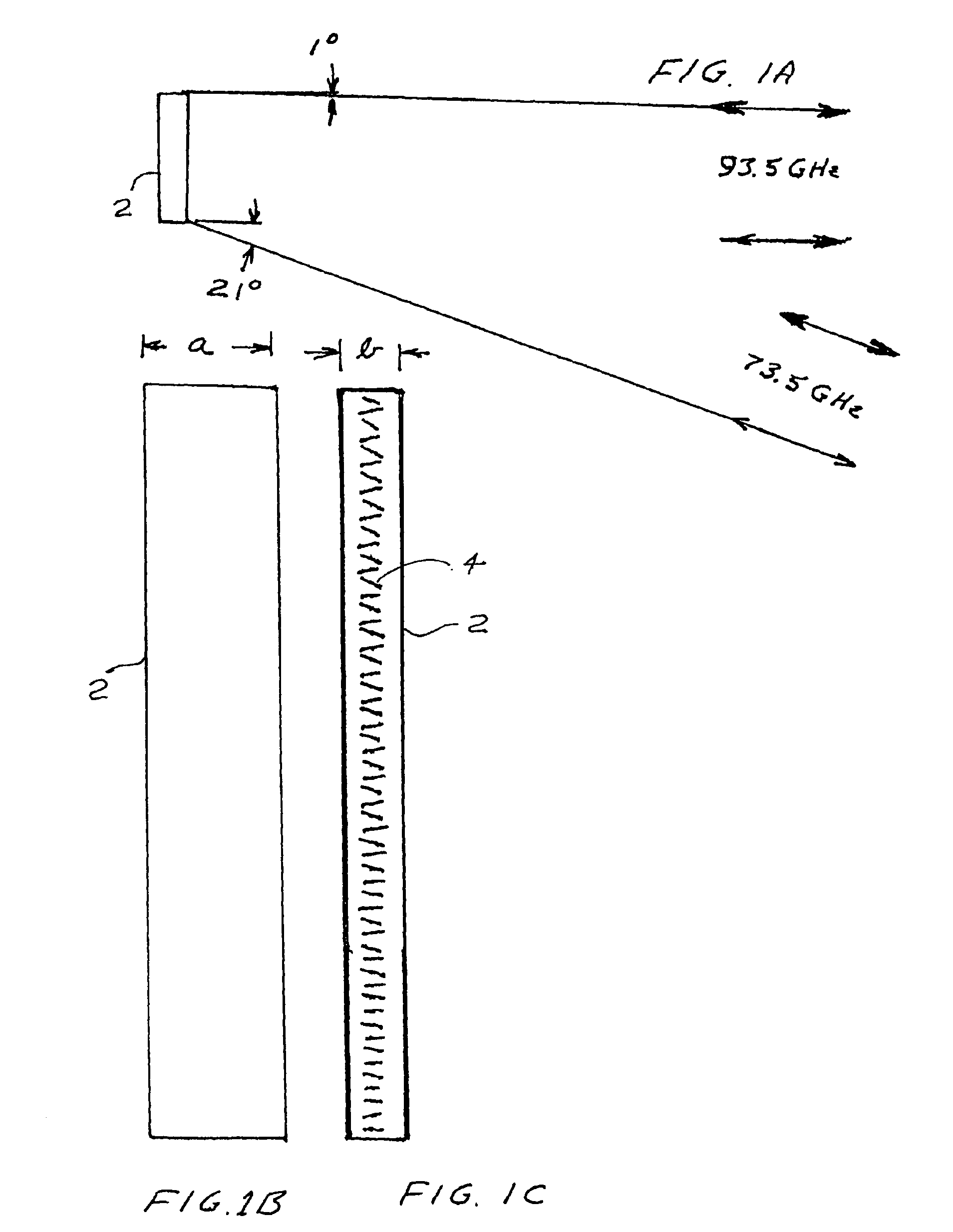
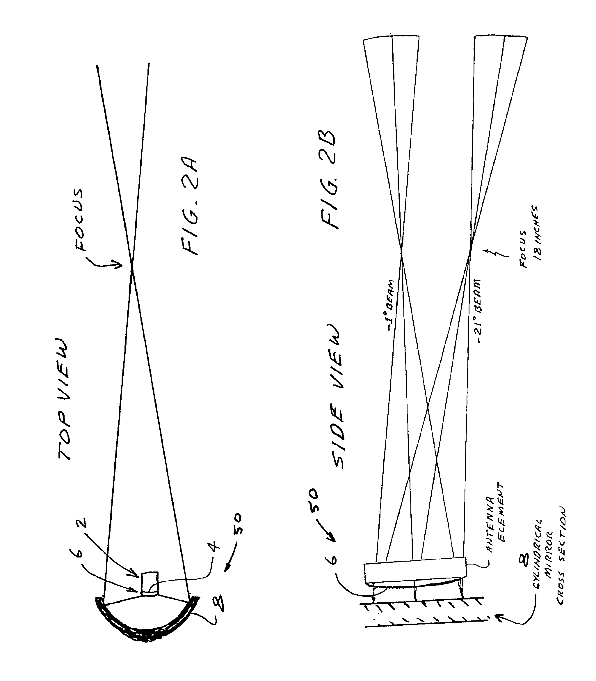
[0014]FIGS. 1A, 1B and 1C are drawings showing features of a one-dimensional millimeter wave antenna according to aspects of the present invention. FIG. 1A shows the elevation field of view of the basic antenna element 2. Each antenna element 2 is constructed of WR-10 waveguide has exterior dimensions a=0.180″, b=0.130″ and interior dimensions a=0.100″, b=0.050″. In fabrication of the antenna, one of the narrow walls is thinned from 40 mils to 6 mils. Then, each WR-10 waveguide antenna has 57 inclined slots 4 cut into its narrow wall at a spacing of 0.079″, which serve as emitting elements. The angle of the slots, and thus the coupling coefficient, increases from 9.66 degrees on the feed end to over 25 degrees at the load end to provide nearly constant field strength along the antenna length. The direction of the angle alternates, providing a “pi” phase shift between successive coupling slots. This geometry creates for a vertical mounted antenna a frequency scan spann...


PUM


Abstract

A millimeter wave imaging system that includes at least one millimeter wave frequency scanning antenna for collecting frequency dependent beams of millimeter wave radiation from a narrow one-dimensional field of view. The collected radiation is amplified at the collected frequencies and the amplified signals are separated into frequency dependent bins with a tapped-delay beam-former. These bins are then sampled to produce a one-dimensional image of the antenna field of view. A two dimensional image of a target may be obtained by moving the target across the field of view of the scanning antenna. In a preferred embodiment the antenna is only 4.5 inches in length and constructed from WR-10 waveguide with inclined slots cut in one of the narrow walls at 79 mil spacings. This geometry creates a frequency-scanned antenna spanning a 20 degree vertical field of view over a 75.5-93.5 GHz operational band of the sensor, starting at approximately 1 degree below horizontal at 93.5 GHz and ranging to approximately 21 degrees below horizontal at 75.5 GHz. In this embodiment 64 of these antenna elements are arranged in four stacks of 16 antennas focused at about 18 inches to construct a portal contraband screener.

Description

[0001]The present invention is a continuation in part of U.S. patent application Ser. No. 09 / 965,875, filed Sep. 28, 2001 which is incorporated by reference herein. The present invention relates to imaging systems and in particular to millimeter wave imaging systems.BACKGROUND OF THE INVENTION[0002]Imaging systems operating at millimeter wavelengths (1 cm to 1 mm; 30 GHz to 300 GHz) are well known. These systems can be important because light at these wavelengths is not completely attenuated by substantial distances of fog or smoke, as is visible light. Light at millimeter wavelengths will also penetrate clothing and significant thickness of materials such as dry wood and wallboard. These millimeter wave imaging systems have therefore been proposed for aircraft to improve visibility through fog and for security applications for detection of hidden weapons and the like. Such systems are described in U.S. Pat. Nos. 5,121,124 and 5,365,237 that are assigned to Applicant's employer. The...

Claims


Application Information

Patent Timeline
Patent Type & Authority Patents(United States)
IPC IPC(8): G01V8/00H01Q3/22H01Q3/26
CPCG01S13/887G01V8/005H01Q1/125H01Q3/22H01Q3/2682H01Q19/10H04B1/3805H04B10/1123H04B10/1149G01S13/44H04B7/0408
Inventor LOVBERG, JOHN A.KOLINKO, VLADIMIR
Owner TREX ENTERPRISE
Why Eureka
Try Eureka