Forward-looking radar system

a radar system and forward-looking technology, applied in the field of radar systems, can solve the problems of high system complexity, low cost, and difficulty in implementing a simple, efficient radar transceiver system that is to be used in mass market applications, and achieve good angular discrimination of reflecting objects, maintain mechanical precision of reflectors, and improve the effect of accuracy

Inactive Publication Date: 2005-12-29
GROENEVELD TRANSPORT EFFICIENCY
View PDF18 Cites 125 Cited by
  • Summary
  • Abstract
  • Description
  • Claims
  • Application Information

AI Technical Summary

Benefits of technology

[0013] Polarized transmitted waves from the transmitting feed are reflected from the radome back to the reflectors, which reflect and rotate the polarization of the transmitted waves so that they penetrate the radome. The transmitted waves exit the radome in a transmission angular-gain distribution pattern that is determined by the location of the transmitting feed in the reflectors and by the shape and orientation of the reflectors with respect to the radome. A reverse process applies to waves reflected from objects in the transmission beam and received by the antenna assembly, each receiving feed forming a respective receive angular-gain distribution pattern. The receiving feeds operate simultaneously and independently of each other. The receiving and transmission feeds are configured so that the combined receive angular-gain distribution pattern is substantially identical to the transmission angular-gain distribution pattern. The folded geometry of the assembly allows design of very shallow antennas, and the plurality of receive radiation patterns gives good angular discrimination of reflecting objects.
[0014] In some preferred embodiments of the present invention, the one or more reflectors are formed as a single molded metallic block. By molding the block at relatively low temperatures, mechanical precision of the reflectors is maintained compared to systems using hot molding, and correction work needed after the molding process is substantially reduced. As further described below, the metallic block may also be used to heat sink other components of the FLR unit.
[0015] The FLR unit further comprises an RF module upon which are mounted mm wave components that are coupled by respective waveguides to the mm wave feeds in the reflectors. The mm wave components typically generate considerable heat. The waveguides are formed as a metallic waveguide manifold, and the RF module is mounted on a back side of the manifold so that the components are aligned with their waveguides and so that they are in good thermal contact with the manifold. The reflectors are mounted on a front side of the manifold, also in good thermal contact with the manifold. The manifold thus acts as an efficient heat sink for the heat generated by the components, and the reflectors effectively also act as part of the heat sink.
[0016] In some preferred embodiments of the present invention, the RF module comprises a metal housing. Monolithic microwave integrated circuits (MMICs) are mounted within the housing, and are coupled to form a mm wave transmitter and a plurality of mm wave receivers. Feeds in the housing allow the passage of mm waves for the transmitter and the receivers, and the housing prevents passage of mm waves through the housing apart from via the feeds. The mm wave transmitter is operated by low frequency (LF) signals transferred via an LF connector through the housing. Some of the MMICs are configured as mixers, so that received mm waves are converted to lower frequencies which may also be transferred via the LF connector through the housing. The housing thus prevents leakage of mm wave radiation
[0017] In order to act as a polarizer, the radome is made from insulating material substantially transparent to mm waves, on which are formed parallel conductive strips. The conductive strips are configured to act as preferential reflectors for mm wave radiation polarized in the direction of the strips. The conductive strips are also coupled to receive an electric current, typically from a battery of the vehicle, and have a resistance so that the strips act as heating elements. When used as heating elements, the strips remove ice and snow from the radome. The strips thus act both as polarizing elements and as heating elements, without reducing the efficacy of either function.

Problems solved by technology

Because of their use in vehicles, the radar systems have to comply with a large number of constraints, such as needing to operate in all weather with virtually no on-going maintenance.
The systems are very sophisticated, yet need to be priced low enough for a mass market environment.
Taken together, the constraints make it difficult to implement a simple, efficient radar transceiver system that is to be usable in a mass market application.
Modem vehicular radars typically require a multi-channel architecture, leading to a complex multi-function antenna and transceiver front end The complexity and stringent requirements on the individual systems typically leads to high cost solutions which limit the applicability of the technology.
This simple procedure fails when there is more than one target in the field of view.
This situation becomes increasingly complex when the number of targets increases and it is further complicated if the targets are not strong enough to be detected in both spectra.
These numerous and complicated algorithms lead to Pfa and (1-Pd) being very dependent on the actual scenarios in the highway, so that in different weather situations and with a large number of objects in the field of view use of the algorithms is questionable if not plainly unsafe.

Method used


Image

  • Forward-looking radar system
  • Forward-looking radar system
  • Forward-looking radar system

Examples


Embodiment Construction

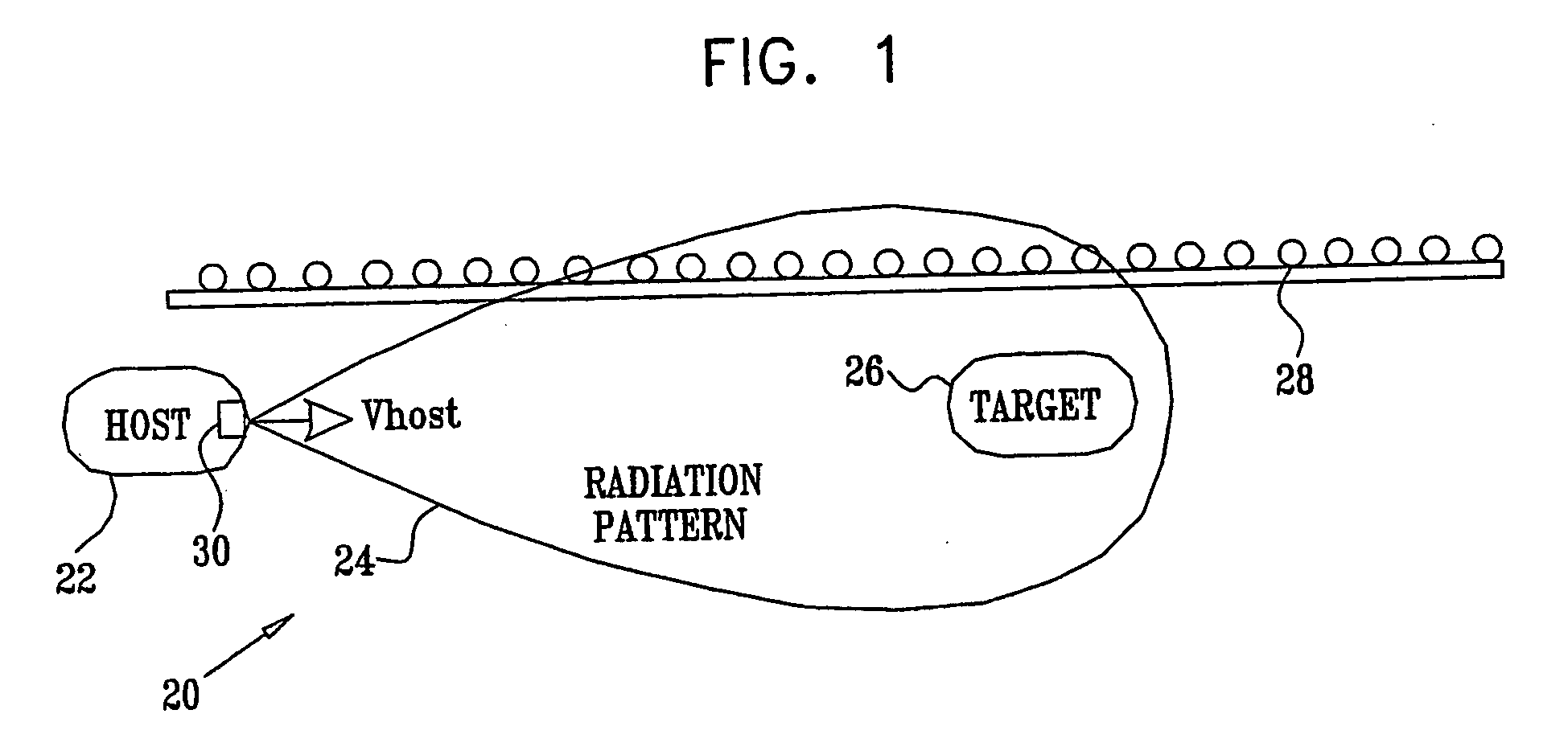
[0096] Reference is now made to FIG. 1, which is a schematic block diagram illustrating use of a forward-looking radar (FLR) unit 30, according to a preferred embodiment of the present invention. FLR unit 30 is preferably mounted on the front of a vehicle 22, and is used to determine moving objects in and near to the path of the vehicle, such as a vehicle 26, herein termed the target vehicle. Unit 30 is also able to detect stationary objects, such as a guard rail 28, in and near to the path of the host vehicle. All such moving and stationary entities that are detectable by FLR unit 30, such as animals, pedestrians, bicycles, cyclists, and those objects exemplified by vehicle 26 and guard rail 28, are herein referred to as automotive targets. Alternatively or additionally, FLR unit 30 may be mounted on the back or side of a vehicle, so as to detect moving or stationary objects behind or beside the vehicle. By way of example, unit 30 is assumed to be mounted on the front of vehicle 22...


PUM


Abstract

An assembly for receiving and transmitting millimeter (mm) waves, including at least one mm wave reflector (84, 86, 88)and at least one mm transmission wave feed (72) configured in a transmission feed location (34) within the at least one mm wave reflector. The assembly also includes a plurality of receiving mm wave feeds (72) configured in respective receiving feed locations (36) within the at least one mm wave reflector; and a radio frequency (RF) module (38). The RF module is coupled to the at least one mm transmission wave feed and to the plurality of the receiving mm wave feeds, so as to drive the at least one mm transmission wave feed to transmit outgoing mm waves and to simultaneously receive incoming mm waves from all of the plurality of the receiving mm wave feeds.

Description

CROSS-REFERENCE TO RELATED APPLICATION [0001] This application claims the benefit of U.S. Provisional Patent Application 60 / 386,893, filed Jun. 6, 2002, which is incorporated herein by reference.FIELD OF THE INVENTION [0002] The present invention relates generally to radar, and specifically to radar systems for use in vehicles. BACKGROUND OF THE INVENTION [0003] Radar systems operating at millimeter wavelengths have been in use for some time on vehicles, where they are installed to provide such features as warnings of objects that may not be visible to a driver of the vehicle, adaptive cruise control (ACC), or warnings of the possibility of a collision. Because of their use in vehicles, the radar systems have to comply with a large number of constraints, such as needing to operate in all weather with virtually no on-going maintenance. The systems are very sophisticated, yet need to be priced low enough for a mass market environment. Taken together, the constraints make it difficult ...

Claims


Application Information

Patent Timeline
Patent Type & Authority Applications(United States)
IPC IPC(8): G01S7/03G01S13/22G01S13/28G01S13/34G01S13/58G01S13/931H01Q1/32H01Q19/17
CPCG01S7/032G01S2013/9385G01S13/282G01S13/343G01S13/345G01S13/582G01S13/584G01S13/931H01Q1/3233H01Q19/17G01S2007/356G01S2007/2883G01S2013/9353G01S2013/9357G01S2013/9375G01S2013/9378G01S13/227G01S2013/9322G01S2013/93274G01S2013/93272G01S2013/932G01S2013/93271G01S7/2883G01S7/356
Inventor HARTZSTEIN, CLAUDIOLEVY, AHARONADAR, DANIELANDERMAN, HANANSHAPIRA, GILFISHLER, EHUDBITTON, ILANSHMUEL, AMIR
Owner GROENEVELD TRANSPORT EFFICIENCY
Why Eureka
Try Eureka