Endoscope apparatus

a technology of endoscope and endoscope, which is applied in the field of endoscope system, can solve the problems of difficult to intuitively grasp the three-dimensional outline of the object of observation, difficult to identify irregularities or the like on the surface of the object, and impracticality of the method

Active Publication Date: 2005-08-30
EVIDENT CORP
View PDF10 Cites 29 Cited by
  • Summary
  • Abstract
  • Description
  • Claims
  • Application Information

AI Technical Summary

Benefits of technology

[0012]In short, an object of the present invention is to provide an endoscope system that makes it easy to designate a cutting plane whose measurem

Problems solved by technology

It is therefore hard to identify the irregularity or the like in the surface of the object.
This poses a problem that it is hard to intuitively grasp the three-dimensional outline of the object of o

Method used


Image

  • Endoscope apparatus
  • Endoscope apparatus
  • Endoscope apparatus

Examples


Embodiment Construction

[0043]Embodiments of the present invention will be described with reference to the drawings below.

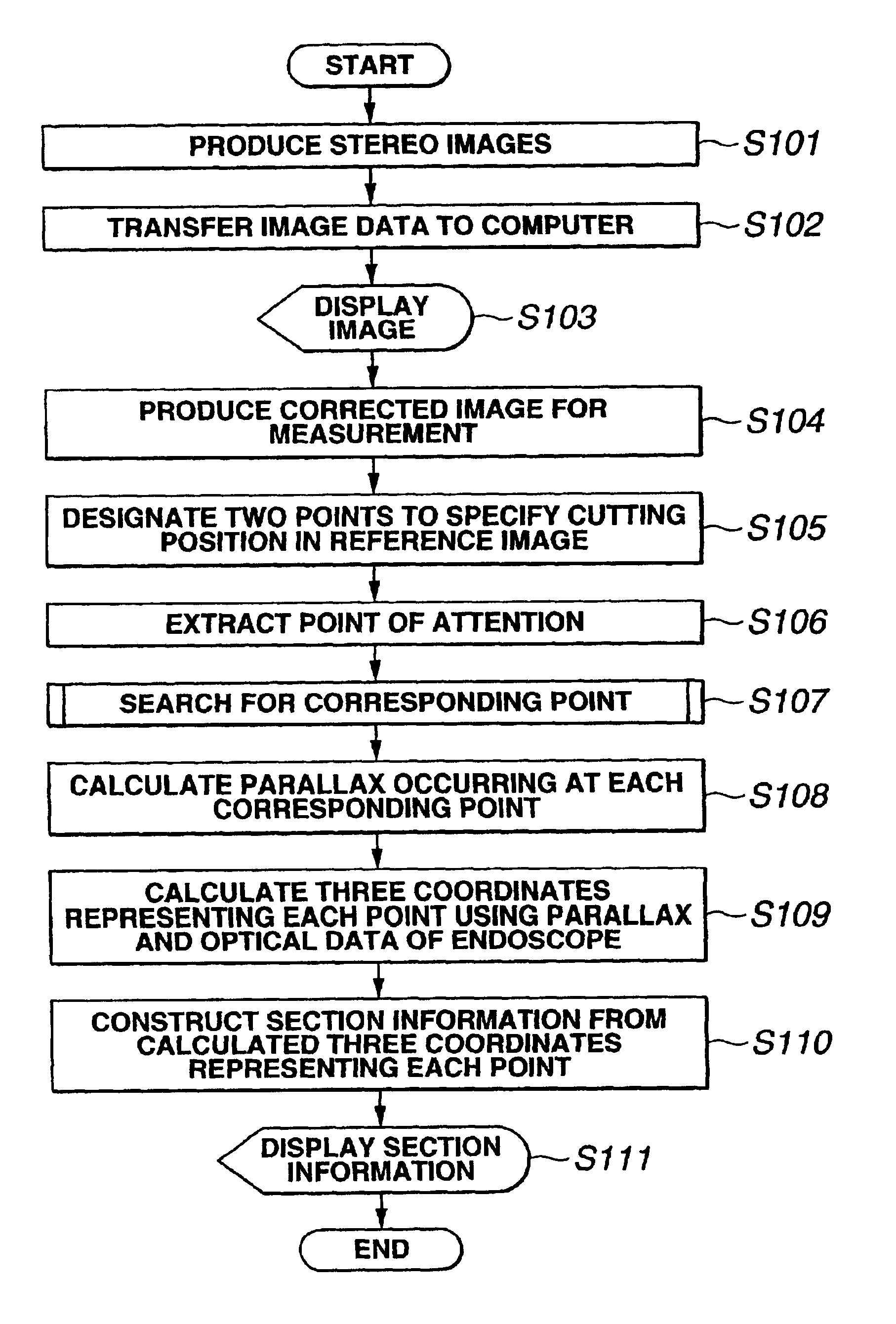
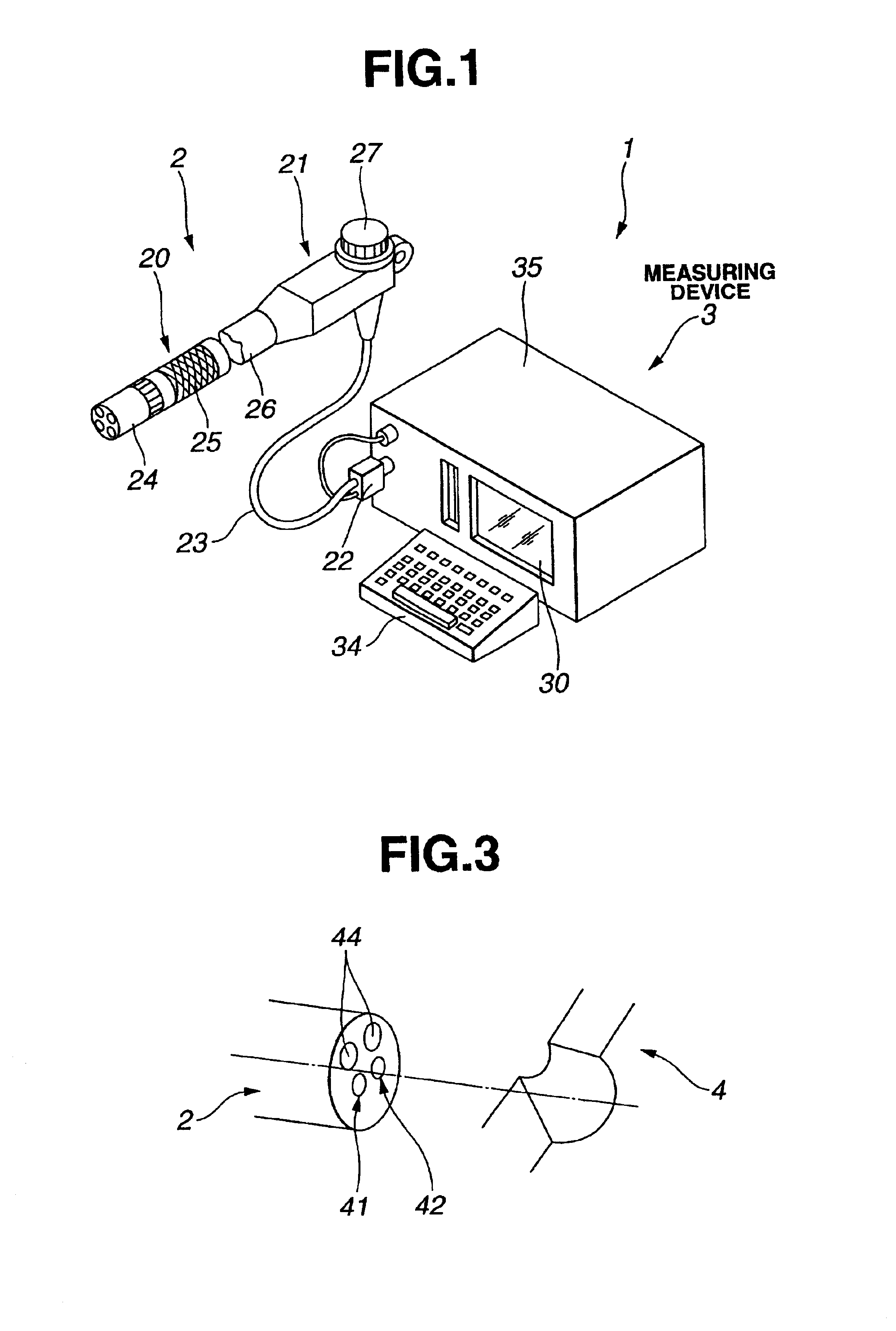
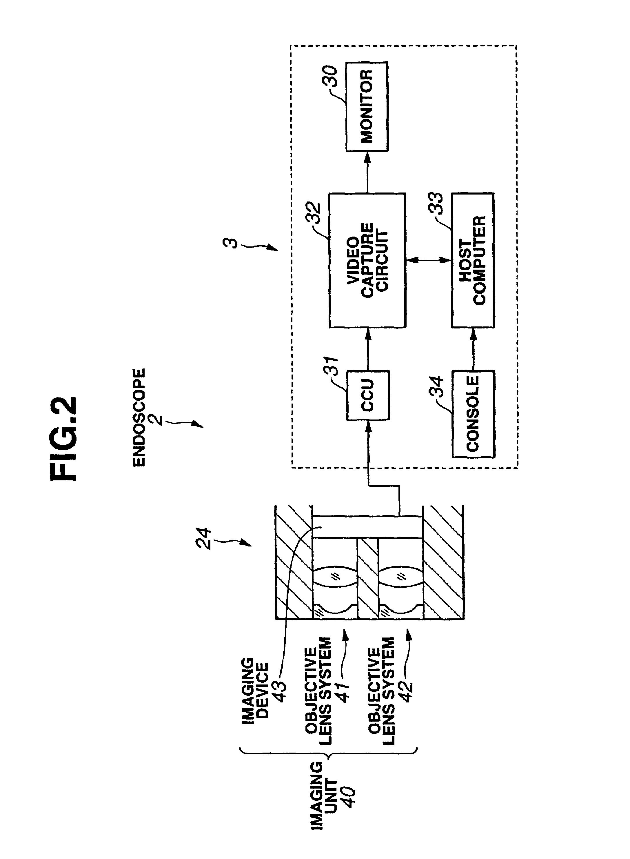
[0044]FIG. 1 to FIG. 15 are concerned with an embodiment of the present invention. FIG. 1 is an explanatory diagram schematically showing the configuration of an endoscope system capable of performing measurement. FIG. 2 is an explanatory diagram showing an imaging unit incorporated in the distal portion of an inserting section of an endoscope and a measuring device having an arithmetic unit. FIG. 3 shows a scene where an object-of-observation region is observed using an endoscope. FIG. 4 is a flowchart describing stereo measurement. FIG. 5 shows an example of an endoscopic image and a cutting-plane reference line displayed on the screen of a monitor by means of an image displaying means. FIG. 6 is an explanatory diagram concerning a cutting plane and a sectional contour line. FIG. 7 shows another example of a reference line. FIG. 8 shows an example of a sectional contour line displayed...


PUM


Abstract

An imaging unit including a pair of objective lens systems and an imaging device that photoelectrically converts optical images into image signals is incorporated in the distal portion of an endoscope. The pair of objective lens systems is arranged to pick up images while viewing an object from different viewing points. Optical images having traveled through the objective lens systems are converged on the imaging device. A camera control unit converts image signals, which result from photoelectric conversion performed by the imaging device, into video signals according to which images are displayed on a monitor. A video capture circuit converts the produced video signals into digital image signals. A host computer performs arithmetic operations using the resultant digital image signals. A desired cutting plane is designated using the reference image displayed on the monitor, whereby section information concerning a viewer's desired section determined with the cutting plane can be acquired.

Description

[0001]The present application claims the benefit of Japanese Patent Application No. Heisei 11-247588 filed in Japan on Sep. 1, 1999, the contents of which are incorporated by reference.BACKGROUND OF THE INVENTION[0002]1. Field of the Invention[0003]The present invention relates to an endoscope system for assisting in objectively assessing the outline of a section of an object, which lies at a desired cutting position, using image signals that represent images picked up by viewing the object from a plurality of viewing points.[0004]2. Description of the Related Art[0005]In recent years, endoscopes have been widely employed in the fields of medicine and industries. Generally, an object appears planar in a view image picked up by an ordinary endoscope. It is therefore hard to identify the irregularity or the like in the surface of the object.[0006]Therefore, for example, Japanese Examined Patent Application Publication No. 8-12332 describes a measuring endoscope system for three-dimens...

Claims


Application Information

Patent Timeline
IPC IPC(8): A61B1/00H04N7/18A61B1/04G02B23/24
CPCA61B1/0005A61B1/00193
Inventor OGAWA, KIYOTOMI
Owner EVIDENT CORP
Why Eureka
Try Eureka