
Electrical power transmission

a technology of power transmission system and power transmission system, applied in the direction of electric devices, instruments, transportation and packaging, etc., can solve the problems of frequent power transfer limits of a power system, significant uncertainties, and concerns about steady-state instability

Inactive Publication Date: 2005-08-30
PSYMETRIX
View PDF6 Cites 10 Cited by
  • Summary
  • Abstract
  • Description
  • Claims
  • Application Information

AI Technical Summary

Benefits of technology

[0016](d) calculating from said relationship power flow limits, providi...

Problems solved by technology

Assuming no thermal limitations, power transfer limits for a power system frequently arise from concerns about transient instability or voltage instability in the event of a contingency.
There are also concerns regarding steady-state instability.
Existing techniques used to provide estimates of a power system's dynamic characteristics, and hence power transfer limits, are based on mathematical dynamic modelling studies which are subject to significant uncertainties.
Hitherto system engineers have had to build in large factors of safety, effectively discounting the safe power transfer capacity by a considerable margin, and thus unduly limiting the power which can be transferred or requiring excess investment in capacity.
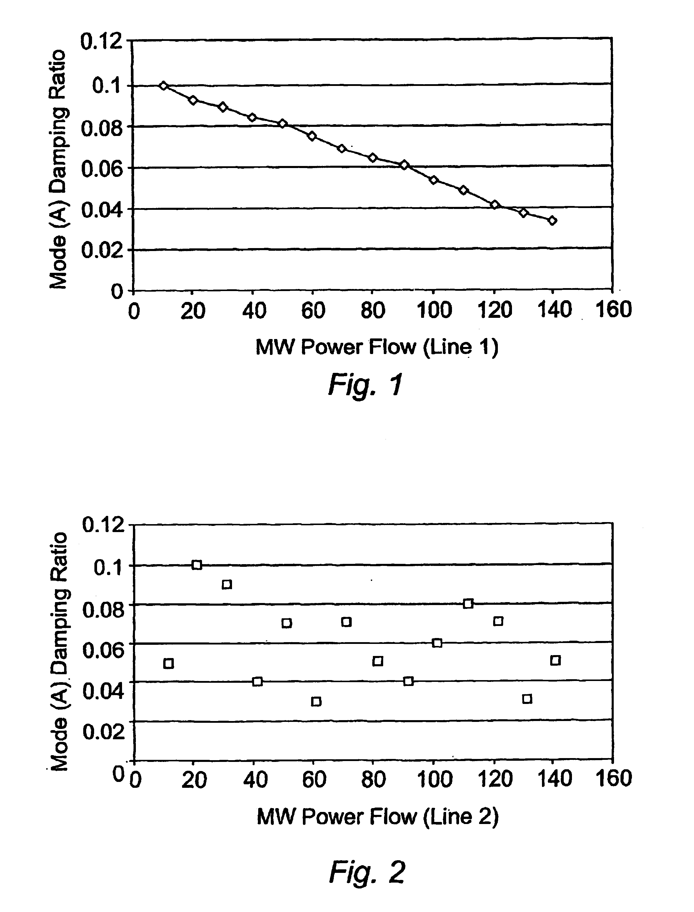
However, these proposals suffer from the facts that:(a) they rely solely on mathematical dynamic modelling, with the attendant problems discussed above(b) the use of “signal energy” without splitting this quantity into frequency components obscures the nature of the problem(c) the relationship between signal energy and / or damping and MW power flow is not, in practice, at all uniform.

Method used


Image

  • Electrical power transmission
  • Electrical power transmission
  • Electrical power transmission

Examples


Embodiment Construction

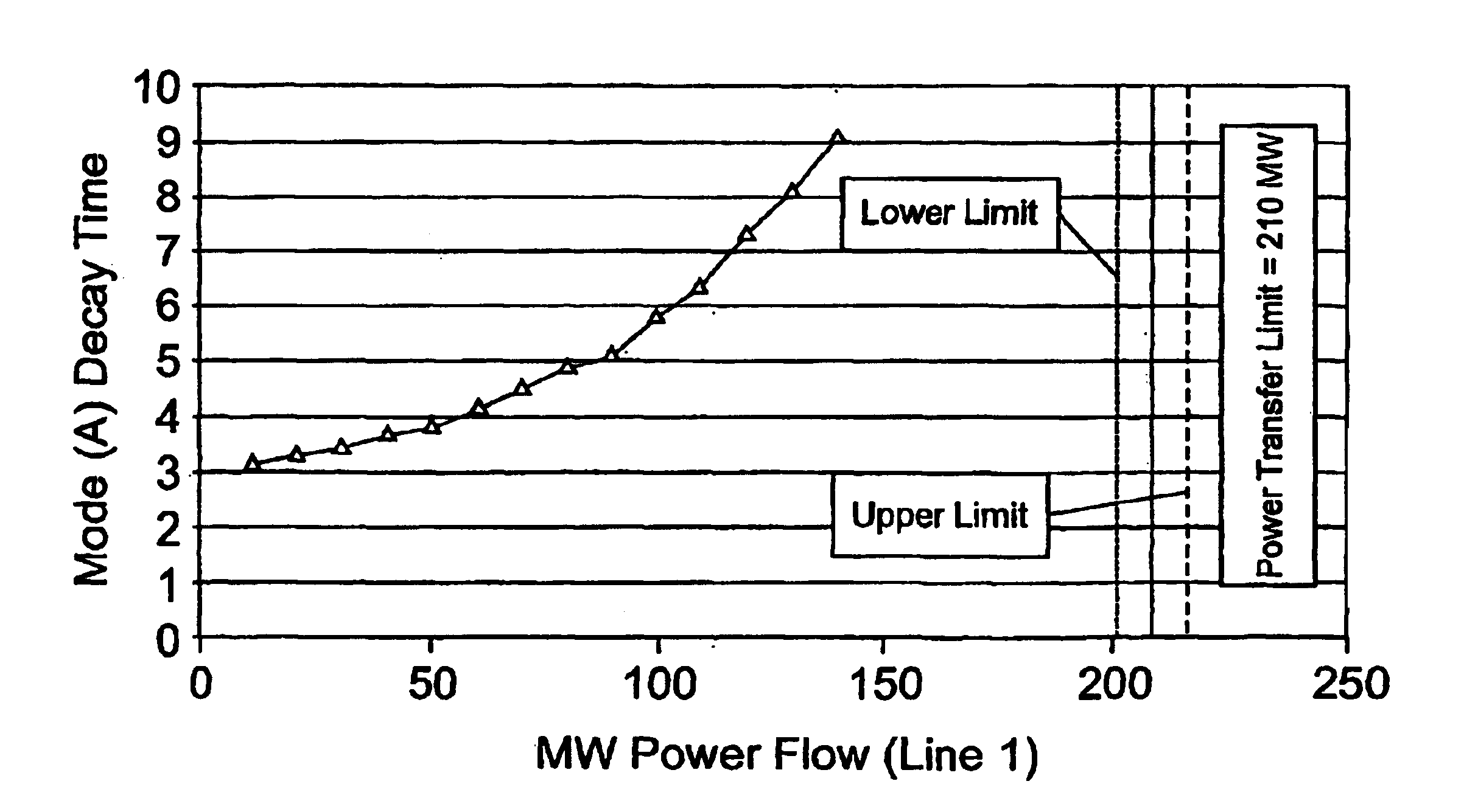
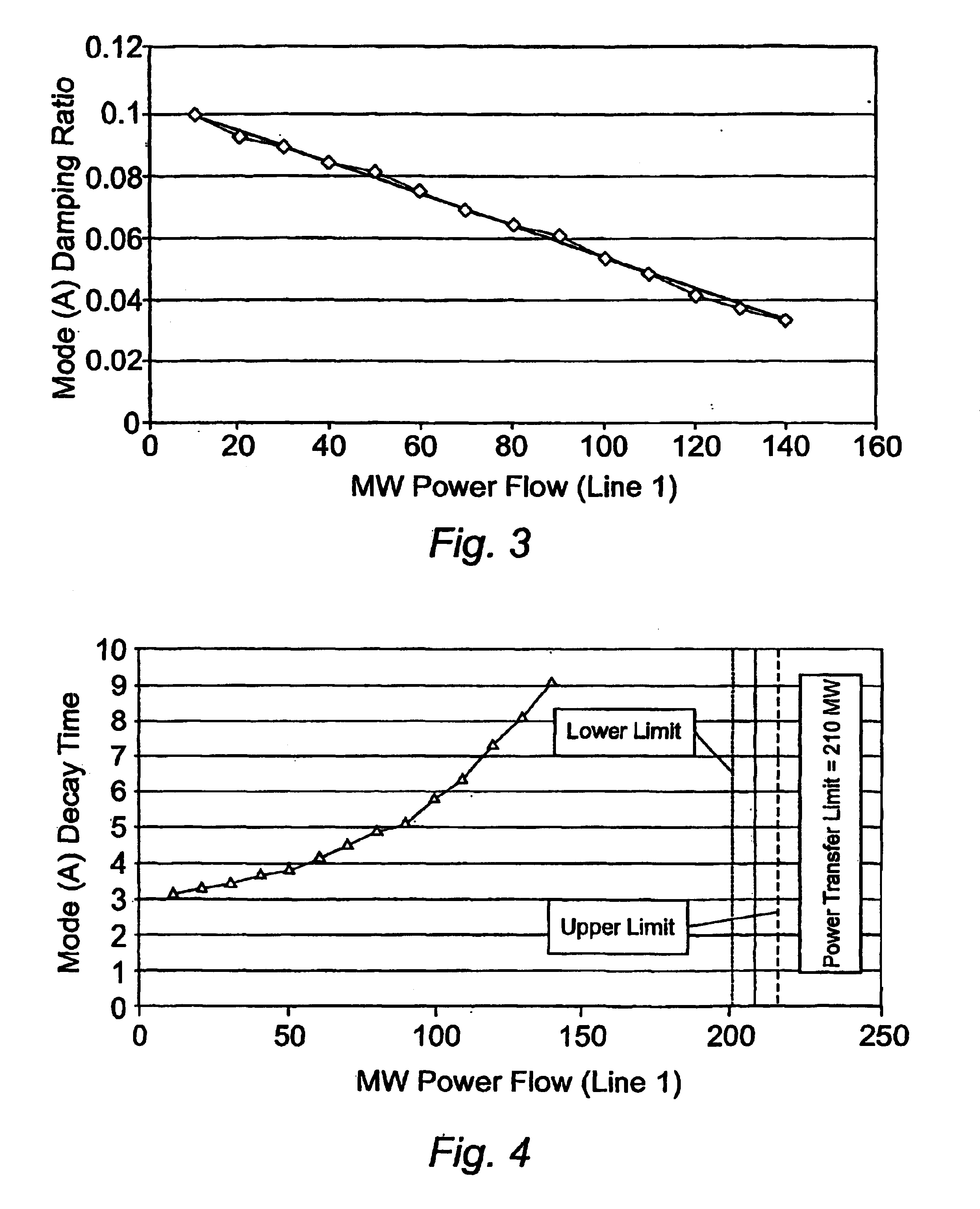
[0022]The method of the invention involves measuring the small signal or steady state dynamic characteristics of the power system. The measurements are obtained continuously and online and are made and associated with the actual prevailing system conditions.

[0023]Specifically, the dynamic characteristics which are measured are the mode damping, mode frequency and mode amplitude of the system based on real or reactive power flow, voltage, system frequency, etc.

[0024]These mode values are in turn associated with the actual prevailing system parameters such as real and reactive power, voltage, system frequency etc.

[0025]In addition, the time of occurrence of the measurements is always taken. These measurements are then used to determine the small signal power transfer limits of the system and thus ensure the most efficient power transfer operational conditions.

[0026]Preferably the measurements are modified by a factor which is determined as follows:

[0027]As a first stage a series of sm...


PUM


Abstract

A method of monitoring a high voltage electrical power system is described in which a system acquires measurements the small perturbations in power system parameters, from which are derived the system dynamic characteristics used to determine power transfer limits that take account of power system prevailing conditions. Further, a method is described that can be used to identify the probable source of power system oscillations that can limit secure power transfer.

Description

RELATED APPLICATIONS[0001]This application is a continuation of International Application No. PCT / GB02 / 02690, filed Jun. 14, 2002, which claims priority to Great Britain Patent Application No.: 0115283.4, filed on Jun. 22, 2001, and so to Great Britain Patent Application No.: 0119398.6, filed on Aug. 9, 2001 and also to Great Britain Patent Application No. 0119400.0, filed on Aug. 9, 2001, the contents of each of which are incorporated by reference herein.FIELD OF THE INVENTION[0002]This invention relates to electrical power transmission systems and particularly to high voltage, high power grid systems.BACKGROUND OF THE INVENTION[0003]Assuming no thermal limitations, power transfer limits for a power system frequently arise from concerns about transient instability or voltage instability in the event of a contingency. There are also concerns regarding steady-state instability. In order to quantify these potential instabilities a knowledge of the power system's dynamic characteristic...

Claims


Application Information

Patent Timeline
IPC IPC(8): H02J3/24H02J13/00H02J3/00
CPCH02J3/24H02J13/0062G01R19/2513Y04S40/124Y02E60/7838H02J13/00016Y02E60/00
Inventor GOLDER, ALEXANDERWILSON, DOUGLAS HARMAN
Owner PSYMETRIX
Learn More