Battery box for railway vehicle

a railway vehicle and battery box technology, applied in the direction of current conducting connection, cell components, coupling device connection, etc., can solve the problems of further affecting the battery box, and difficult to obtain a small-sized battery, so as to achieve fine adjustment

Active Publication Date: 2005-09-06
KAWASAKI RAILCAR MFG CO LTD
View PDF5 Cites 36 Cited by
  • Summary
  • Abstract
  • Description
  • Claims
  • Application Information

AI Technical Summary

Benefits of technology

[0013]In accordance with the above construction, when the movable tray (battery) is pulled out from and put into the battery box for the purpose of maintenance, such as liquid level check, cleaning, charging, and replacement of the battery, electric connection and disconnection between the wire within the casing and the battery wire is achieved by using connectors. By doing so, it is not necessary for the wire (electric wire) to have an extra length sufficient to move together with the movable tray. When the movable tray is pulled out from an inside of the casing (battery box) for the purpose of maintenance, the movable tray equipped with the battery (including the battery wire), is completely separated from the casing by separating the connectors. Therefore, a space in which the wires having an extra length are stored becomes unnecessary, and the battery box is advantageously small-sized.
[0014]When the movable tray is stored, the movable tray is guided by the guide means to cause the connector to be connected to the receiving connector. So, fine adjustment is sufficient in alignment by the aligning means, and the connector can be electrically connected to the receiving connector smoothly.

Problems solved by technology

Under the circumstances, it is difficult to make the battery box small-sized.
In this case, the movable tray (battery) may interfere with the battery box.
A space for permitting this movement makes it further difficult to obtain a small-sized battery.
On the other hand, when the movable tray is horizontally moved onto the table lift without being lifted up, a gap between the up-down table and the battery box is not constant, and a course of the movable tray moving on the table lift varies, so that movement of the movable tray is not stabilized.
In particular, such a varying course of the movable tray is problematic, because the battery has a heavy weight.

Method used


Image

  • Battery box for railway vehicle
  • Battery box for railway vehicle
  • Battery box for railway vehicle

Examples


Embodiment Construction

[0035]Hereinafter, an embodiment of the present invention will be described with reference to the drawings.

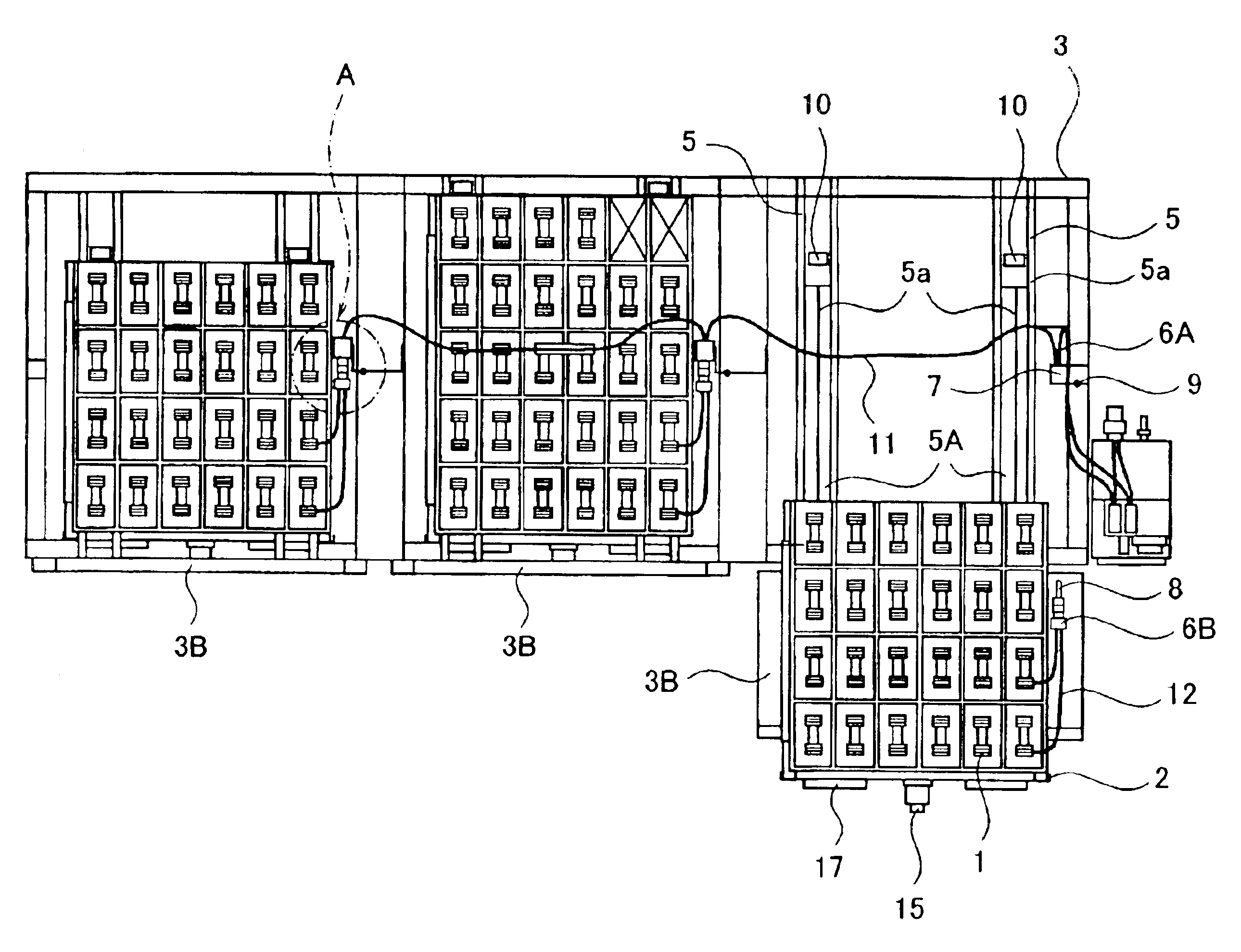
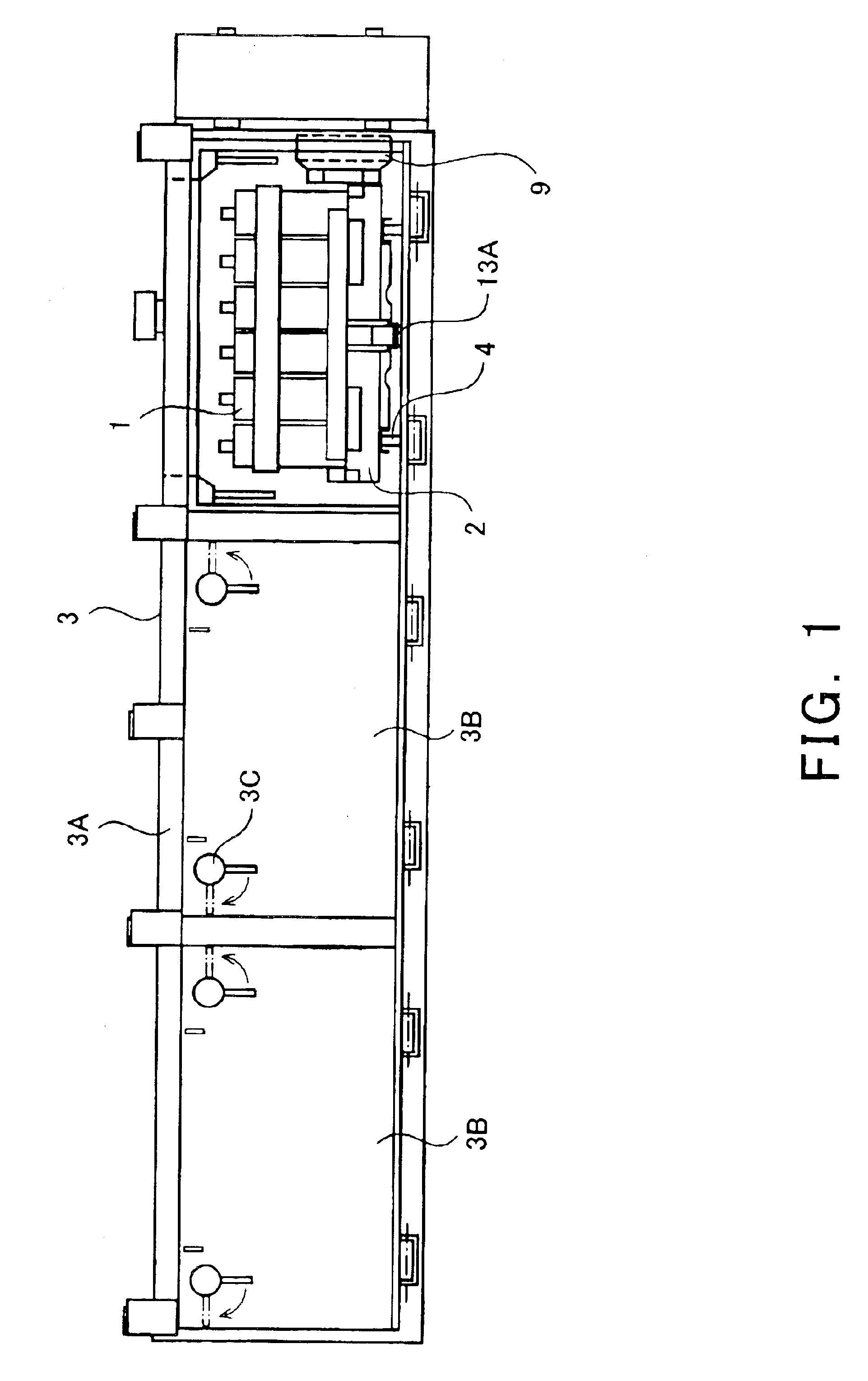
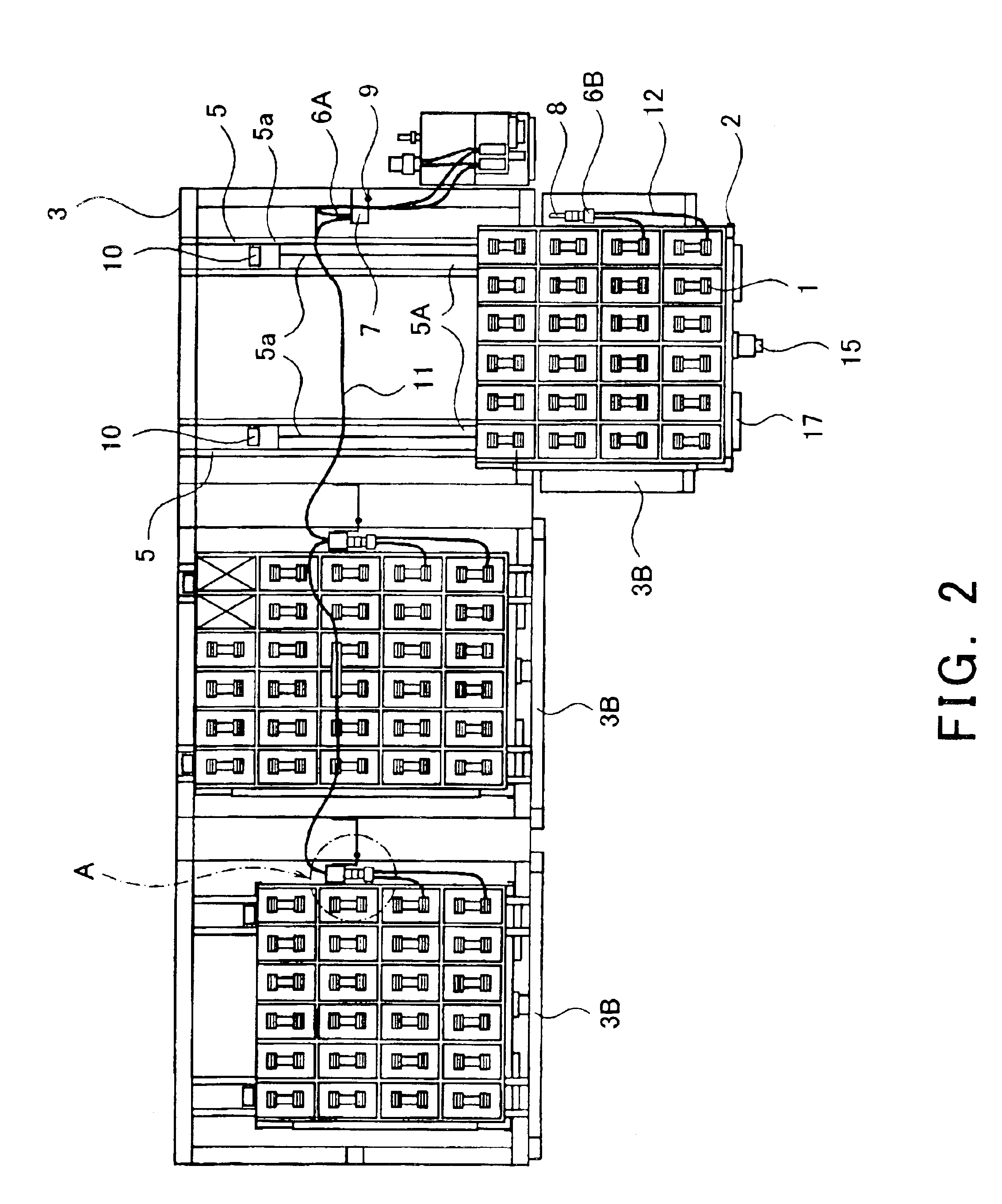
[0036]FIG. 1 is a front view showing a state in which a movable tray is stored within a battery box for a railway vehicle according to the present invention, with one of lid members removed. FIG. 2 is a plan view showing a state in which the movable tray is pulled out with one of the lid members being open, with a box ceiling plate (plate that covers a box from above) removed.

[0037]As shown in FIGS. 1 and 2, a battery 1 is equipped on a movable tray 2, and stored in a battery box 3 mounted under a floor of a car body of a railway vehicle. It should be appreciated that the size of the movable tray 2 is changed depending on the volume of the battery 1 equipped on the movable tray 2, for example, the number of battery cells.

[0038]The battery box 3 is comprised of a casing 3A having a face configured to open horizontally and a lid member 3B pivotable around a hinge (not shown) at a...


PUM

PropertyMeasurementUnit
electricallyaaaaaaaaaa
forceaaaaaaaaaa
electric poweraaaaaaaaaa

Abstract

A receiving connector 6A and upper and lower guide sockets 7 are mounted on an attachment 9, and the attachment 9 is mounted on a casing 3A by way of a bolt member 16 so that positioning of the attachment 9 is adjustable. Guide rails 5A guide wheels 4 of the movable tray 1 having a connector 6B. Upper and lower guide pins 8 are respectively inserted into the upper and lower guide sockets 7 to be guided. Thereby, the attachment 9 is moved and connectors 6A and 6B are smoothly connected to each other while being aligned.

Description

BACKGROUND OF THE INVENTION[0001]1. Field of the Invention[0002]The present invention relates to a battery box for a railway vehicle that stores a battery as an emergency power source.[0003]2. Description of the Related Art[0004]In general, a railway vehicle is equipped with a battery as an emergency power source to maintain functions such as ventilation within a cabin or lighting within a passenger cabin for a certain time even when supply of an electric power from an electric-car line is cut off or supply of an electric power is cut off due to breakdown of a generator or the like. The battery is typically stored in a battery box mounted on a car body.[0005]In the conventional battery box used in a railway vehicle (e.g., Japanese Utility Model Publications Nos. Sho. 63-46374 and Sho. 63-30674), a movable tray (inner tray) on which a battery is equipped is pulled out from an inside of a casing of the battery box by opening a lid provided on a front face of the casing. The movable tr...

Claims


Application Information

Patent Timeline
Patent Type & Authority Patents(United States)
IPC IPC(8): B61C17/12B61C17/00B61D27/00B61D17/00B61D49/00H01M2/10H01R13/62B60K1/04B61C17/06H01M50/209H01M50/249H01M50/262H01M50/271H01M50/298H01M50/50H01R13/629H01R43/26
CPCB61C17/06H01M2/1083H01M2/20H01R13/629H01R43/26Y02T30/18Y02T30/00Y02E60/10H01M50/50H01M50/249H01M50/209H01M50/262H01M50/271H01M50/298
Inventor TAMAKI, HISATAKAHIRAOKA, NAOHIRO
Owner KAWASAKI RAILCAR MFG CO LTD
Why Eureka
Try Eureka