Door handle device

a door handle and handle technology, applied in the direction of display/control unit casings, pulse techniques, electrical apparatus casings/cabinets/drawers, etc., can solve the problems of not being able to perform the push-operation of the operation button, not being able and being unable to ensure the normal operation of the tact switch. , to achieve the effect of preventing ingress and reducing the size of the door handle devi

Active Publication Date: 2020-03-24
TOKYO PARTS IND CO LTD
View PDF16 Cites 0 Cited by
  • Summary
  • Abstract
  • Description
  • Claims
  • Application Information

AI Technical Summary

Benefits of technology

[0028]According to one mode of embodiment of the door handle device of the present invention, the switch component is directly fastened to the top face of the circuit board and therefore lead wires for connecting the printed wires on the circuit board to the terminals of the switch component are unnecessary, such that space for routing the lead wires will be unnecessary, whereby the size of the door handle device can be reduced. Furthermore, the operation projection, which faces the switch component, is inserted into the insertion opening in the roof, the structure being such as to guide the pushing direction of the pushbutton, whereby the switch component can be reliably operated, even in the event of pushing from an oblique lateral direction.
[0029]Furthermore, according to one embodiment of the door handle device of the present invention, the bottom end face of the tubular part of the switch case that covers the switch component abuts the circuit board, the switch case that covers the switch component is united with the pushbutton for operating the switch component, and the pushbutton flange is brought into close contact with the roof of the switch case all the way therearound. Consequently, it is possible to effectively prevent ingress of potting agent, foreign matter or water droplets into the switch case, or into the space between the switch case and the pushbutton, allowing normal operation of the switch component in accordance with push-operations of the pushbutton to be ensured.

Problems solved by technology

However, with the handle device described in Japanese Patent Laid-Open Publication No. 2015-25261, the button is separated from the switch cover and the hold down member, and thus problems such as the following may occur.
First, there is a risk of the potting agent flowing between the operation button and the hold down member when filling with the potting agent, and supposing that the potting agent were to flow between these, it might not be possible to ensure normal operation of the tact switch in accordance with the push-operations of the operation button.
Furthermore, there is a risk of foreign matter getting between the operation button and the hold down member prior to the cover member being mounted on the handle main body, and thus it may not be possible to ensure normal operation of the tact switch in accordance with the push-operations of the operation button.
Furthermore, there is a possibility of ingress of water droplets between the operation button and the hold down member when the vehicle is used and, if these water droplets freeze in a cold climate, there is a risk of not being able to perform the push-operations of the operation button.
Furthermore, the handle device described in Japanese Patent Laid-Open Publication No. 2015-25261 does not have a structure that guides the pushing direction of the operation button, and therefore the operability of the tact switch may be inferior in cases where, for example, the operation button is pushed from an oblique lateral direction.

Method used


Image

  • Door handle device
  • Door handle device
  • Door handle device

Examples


first exemplary embodiment

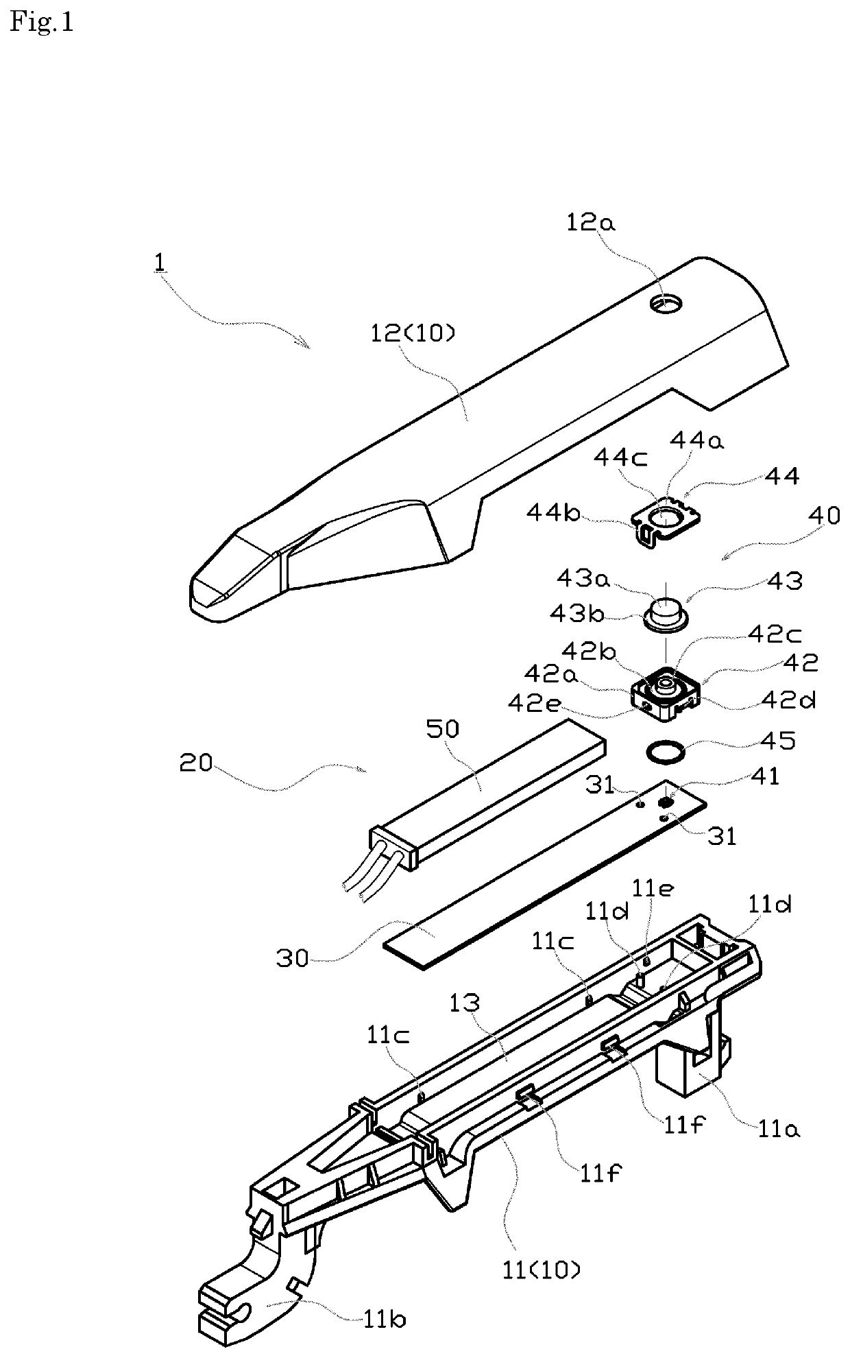
[0039]The configuration of the door handle device in this example will be described using FIG. 1 through FIG. 5.

[0040]The door handle device 1 in this example is mounted on the outer panel of a vehicle door so as to allow for opening and closing operations of the vehicle door from the outside, and is provided with a door handle 10 and a control unit 20.

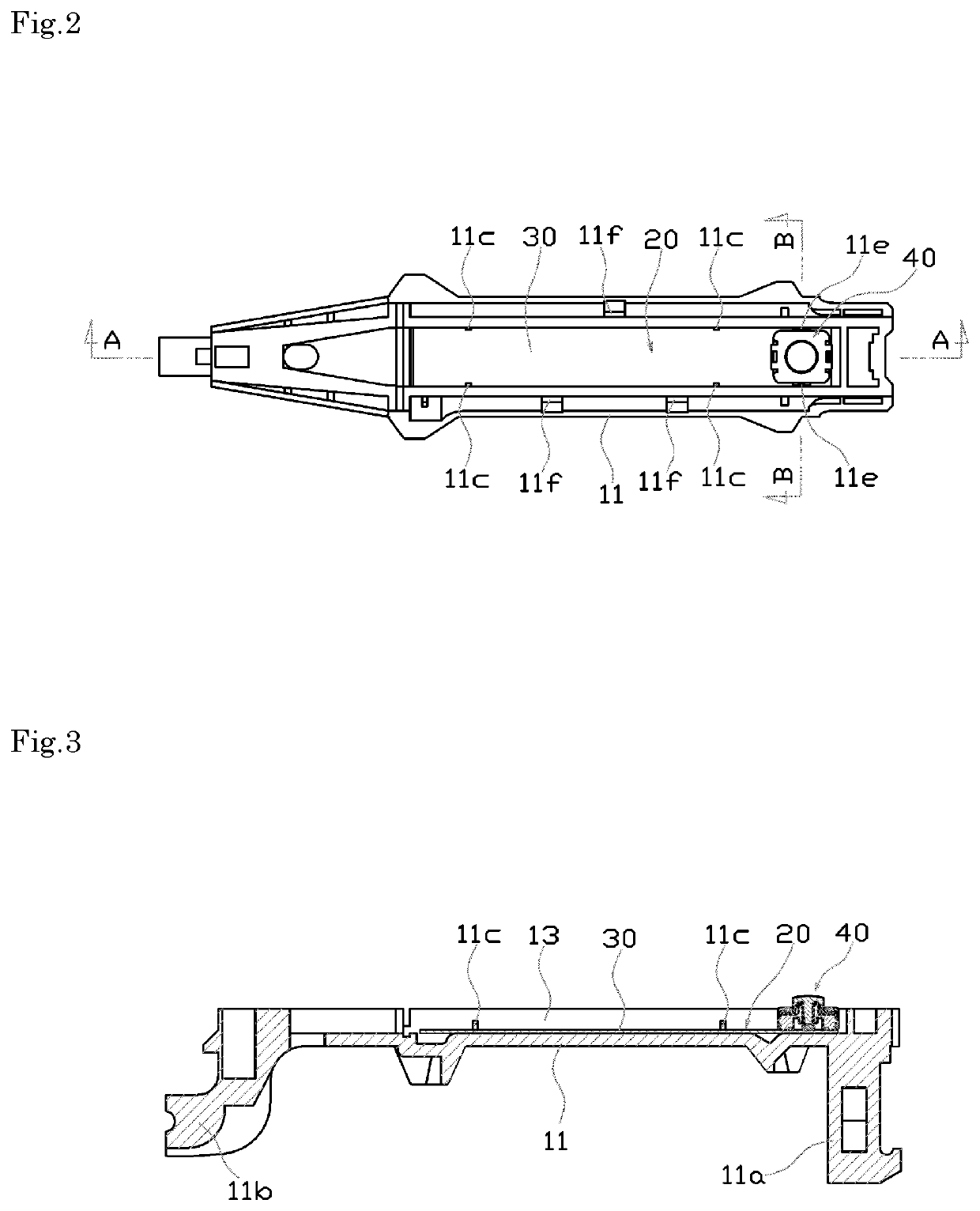
[0041]The door handle 10 comprises a first handle member 11 and a second handle member 12, which are formed from a synthetic resin, in shapes that are elongate in the front / rear direction of the vehicle body, and housing space 13, which is elongate in the front / rear direction of the vehicle body, is formed at the interior thereof.

[0042]The first handle member 11 is integrally provided with an operating part 11a and a support part 11b, at the front end and the rear end thereof, respectively, which penetrate into the outer panel of the vehicle door. This first handle member 11 is mounted on the outer panel so as to extend in the front / r...

second exemplary embodiment

[0081]The configuration of the door handle device in this example will be described using FIG. 6. In FIG. 6, constituent parts that are the same as in the first exemplary mode of embodiment are given the same reference numerals, and redundant description thereof is forgone.

[0082]In this example, the major differences with respect to the first exemplary embodiment reside in the following two points.

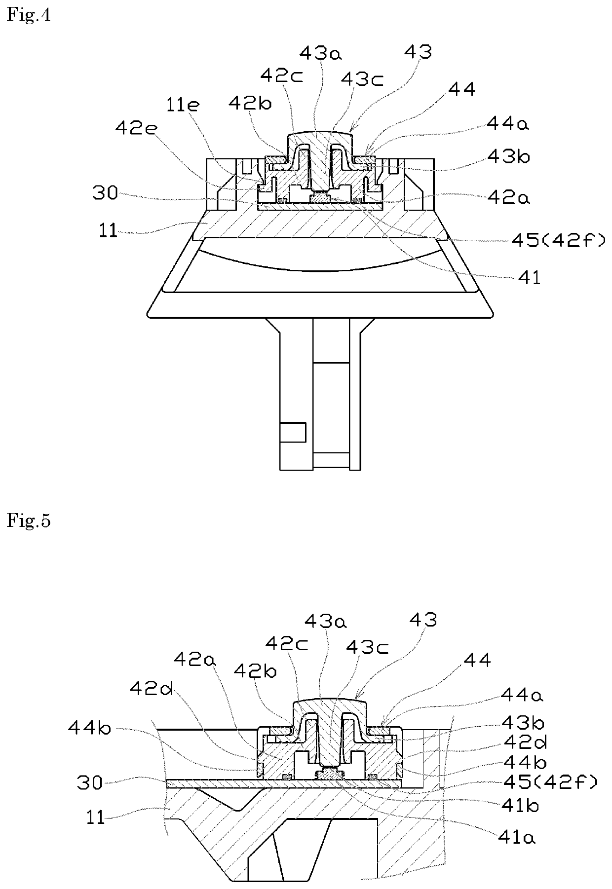
[0083]First, in the switch case 42 in the first exemplary mode of embodiment, an annular protrusion 42c is formed so as to protrude, in both the upward direction and the downward direction, from the roof 42b, but in the switch case 42 in the present example, an annular protrusion 42c is formed so as to protrude only in the downward direction from the roof 42b.

[0084]Furthermore, in the pushbutton 43 in the first exemplary embodiment, a substantially columnar operation projection 43c is formed, but with the pushbutton 43 in the present example, a striking part 43d, having a larger diameter ...

third exemplary embodiment

[0088]The configuration of the door handle device in this example will be described using FIG. 7. In FIG. 7, constituent parts that are the same as in the first exemplary mode of embodiment are given the same reference numerals, and redundant description thereof is forgone.

[0089]In the first exemplary embodiment, the flange 43b on the pushbutton 43 was brought into close contact with the roof 42b by the cover member 44, but in the present example, the flange 43b on the pushbutton 43 is brought into close contact with the roof 42b by the second handle member 12, without using the cover member.

[0090]For this reason, in the present example, an annular projection 12b, which protrudes downwards, is provided at the periphery of the opening 12a in the second handle member 12, and a structure results with which, as a result of joining the second handle member 12 to the first handle member 11, the annular protrusion 12b pushes the flange 43b on the pushbutton 43 all the way therearound, so a...


PUM


Abstract

A control unit 20, including a circuit board and a switch unit, is arranged in a housing space in a door handle. The switch unit has a switch component, which is fastened to the circuit board, a hard switch case, which covers the switch component, a soft pushbutton, which operates the switch component, and a hard cover member, which is fastened to the switch case. The pushbutton has a pushing part in the shape of a cap, a flange, which extends from the bottom end of the pushing part, and an operation projection, which is inserted into an insertion opening in a roof. The switch case and the pushbutton are united by the cover member, and the flange is brought into close contact with the roof all the way therearound, by the cover member.

Description

BACKGROUND OF THE INVENTION[0001]The present invention relates to a door handle device that can be mounted, for example, on the outer panel of a vehicle door.[0002]Japanese Patent Laid-Open Publication No. 2015-25261 describes a vehicle door handle device, wherein a vehicle door is provided with an operating handle comprising a handle main body having an housing recess for housing and fastening a board on which an electronic component such as a tact switch is mounted, and a cover member, which is joined to the handle main body so as to cover this housing recess, in which a tact switch, which switches switching modes in accordance with push-operations of an operation button facing the outer surface of the cover member, is electrically connected to a printed circuit on the board, and fastened accommodated within the housing recess, the interior of the housing recess being filled with a potting agent.[0003]With the handle device described in Japanese Patent Laid-Open Publication No. 20...

Claims


Application Information

Patent Timeline
Patent Type & Authority Patents(United States)
IPC IPC(8): E05B85/16H05K5/02H05K5/00H03K17/96E05B77/34H01H13/14H01H13/50E05B81/76E05B81/78
CPCE05B81/76H01H13/14H05K5/0239H01H13/50E05B77/34H03K17/962H05K5/0217E05B81/77H05K5/0017E05B85/16H03K2217/960755E05B81/78E05B85/08E05B85/085H05K5/03
Inventor KITAHARA, TAKAHISA
Owner TOKYO PARTS IND CO LTD
Why Eureka
Try Eureka