Arrangement for liquid cooling an electrical assembly using assisted flow

a technology of electrical assemblies and arrangement, applied in the direction of positive displacement liquid engines, semiconductor/solid-state device details, lighting and heating apparatus, etc., can solve the problems of inability to use assisted cooling techniques, maintenance problems, and insignificant amount, and achieve the effect of increasing the liquid's ability to dissipate hea

Inactive Publication Date: 2005-09-06
LUCENT TECH INC +1
View PDF18 Cites 73 Cited by
  • Summary
  • Abstract
  • Description
  • Claims
  • Application Information

AI Technical Summary

Benefits of technology

[0005]The present invention fulfills the above needs, as well as others, by providing an arrangement for cooling an electrical assembly that includes a circuit board at least partly disposed in a fluid tight compartment formed by an enclosure. The circuit board divides the compartment into first and second subcompartments. The circuit board includes at least one mechanical actuator that assists the flow of liquid from one subcompartment to another through at least one aperture in the circuit board. The assisted flow of liquid through the aperture allows liquid that has been heated from one or more electrical components in one subcompartment to flow to another compartment. Such flow of the heated liquid increases the liquid's ability to dissipate the heat.

Problems solved by technology

One problem encountered with these electronic assemblies, as well as other types of electronic assemblies, is that their high speed operations generate a significant amount of heat which can be detrimental to the electronic assemblies and thus cause maintenance problems.
However, the use of assisted cooling techniques are discouraged by the communications industry because assisted cooling techniques can introduce a hazard to technicians working in the area.
For example, the use of large fans can undesirably create a hazardous noise level.
In addition, the types of fans used in assisted cooling tend to break down and thus increase the maintenance problems associated with servicing the telecommunications network.

Method used


Image

  • Arrangement for liquid cooling an electrical assembly using assisted flow
  • Arrangement for liquid cooling an electrical assembly using assisted flow
  • Arrangement for liquid cooling an electrical assembly using assisted flow

Examples


Embodiment Construction

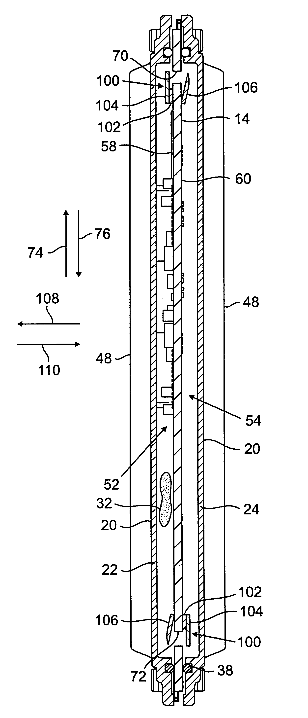
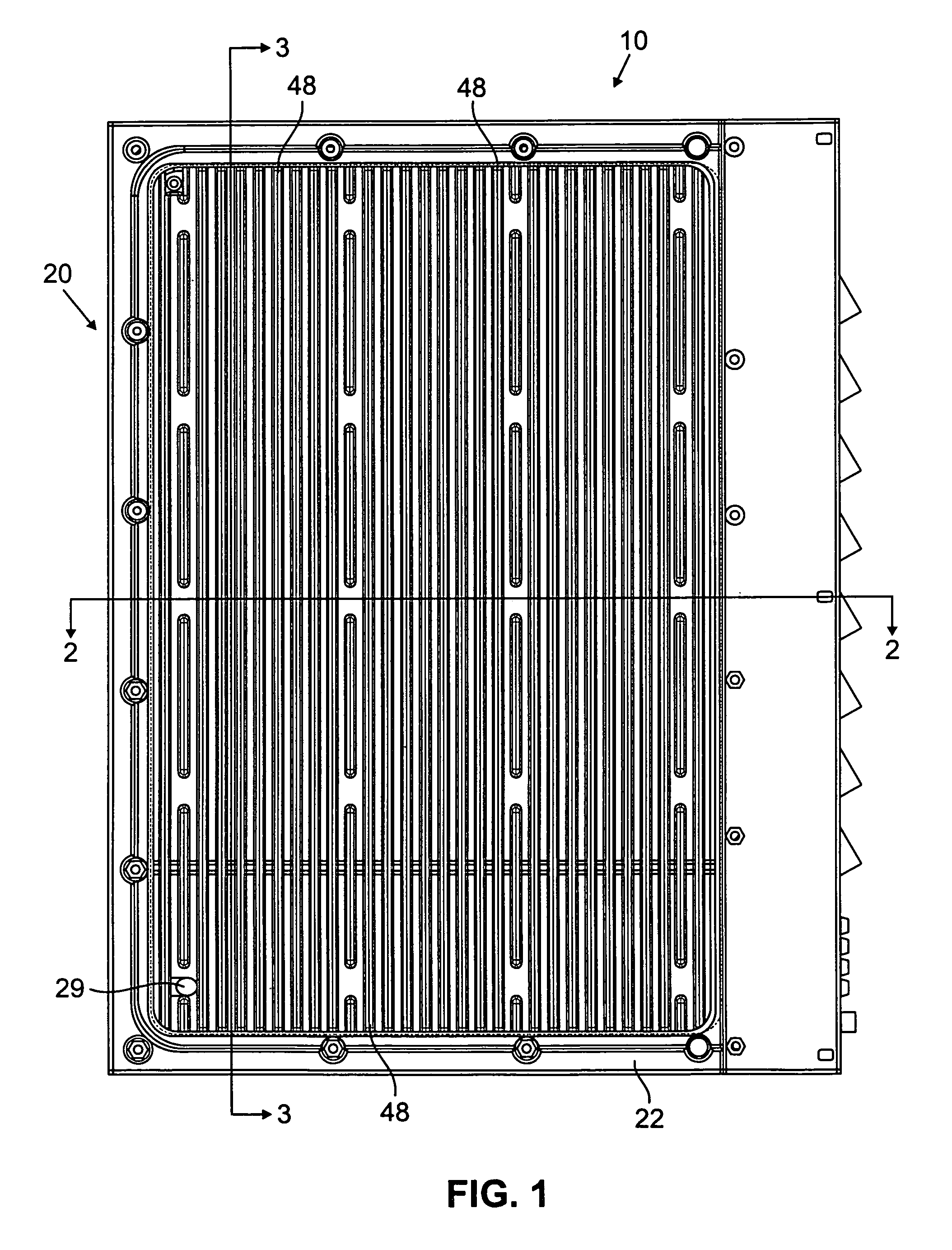
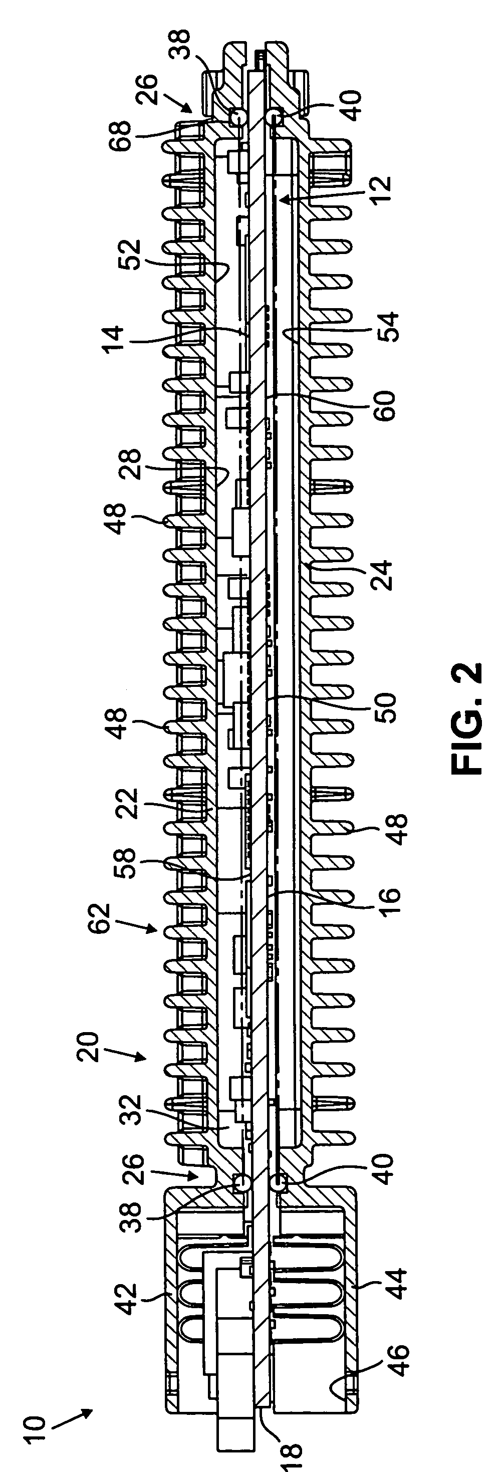
[0020]Referring to FIGS. 1, 2, 3, 4, 5, 6, 7A and 7B there is shown an exemplary arrangement 10 for cooling an electronic assembly 12 which incorporates the features of the present invention therein. The arrangement 10 includes an enclosure member 20, a circuit board 14 and at least one electromechanical actuator, shown in FIGS. 3 and 4 as plural electromechanical actuators 100. In accordance with the present invention, the circuit board 14 includes at least one aperture, shown by way of example as the upper apertures 70, for facilitating liquid flow from a first subcompartment 52 to a second subcompartment 54 to assist in cooling of electrical components on the circuit board 14 (see generally FIG. 6). As illustrated in FIGS. 3, 4 and 5, the apertures 70 are hidden from view by portions of the electromechanical actuators 100.

[0021]In general, the plurality of electronic components includes switching devices, power management devices, filter devices, memory devices, and processor dev...


PUM


Abstract

An arrangement for cooling an electronic assembly includes a circuit board, an enclosure member and at least one electromechanical actuator. The circuit board has a first surface, a second surface, and at least a first heat-generating element secured to the first surface. The circuit board further comprises at least one aperture extending between the first surface and the second surface. The enclosure member is secured to the circuit board so as to form a fluid tight barrier of a compartment defined at least in part by the enclosure member. The compartment includes a first subcompartment defined at least in part by the first surface and the enclosure member and a second subcompartment defined at least in part by the second surface and the enclosure member. The at least one electromechanical actuator is secured within the fluid type barrier and is operable to generate a flow movement in the direction of the at least one aperture when liquid is disposed in the fluid tight barrier.

Description

FIELD OF THE INVENTION[0001]The present invention relates generally to arrangements for cooling electronic assemblies, and more particularly, to arrangements for liquid-cooling such assemblies.BACKGROUND OF THE INVENTION[0002]Electronic assemblies which include a circuit board having a plurality of electronic components attached thereto are widely used in the communications industry to manage the flow of data on a telecommunications network. These electronic assemblies must be able to manage a high data rate over significant periods of time (e.g., months) without any maintenance. One problem encountered with these electronic assemblies, as well as other types of electronic assemblies, is that their high speed operations generate a significant amount of heat which can be detrimental to the electronic assemblies and thus cause maintenance problems. As a result, these electronic assemblies must be cooled constantly in order to maintain acceptable operating temperatures to avoid mainten...

Claims


Application Information

Patent Timeline
Patent Type & Authority Patents(United States)
IPC IPC(8): H05K7/20
CPCH05K7/20636
Inventor BORTOLINI, JAMES R.FARLEIGH, SCOTT E.GRIMES, GARY J.NYQUIST, JEAN S.SHERMAN, CHARLES J.
Owner LUCENT TECH INC
Why Eureka
Try Eureka