Full thickness resectioning device

a resection device and full thickness technology, applied in the direction of surgical staples, surgical forceps, paper/cardboard containers, etc., can solve the problems of adding substantially to the discomfort of patients and the recovery time associated with the procedur

Inactive Publication Date: 2005-09-06
BOSTON SCI SCIMED INC
View PDF15 Cites 304 Cited by
  • Summary
  • Abstract
  • Description
  • Claims
  • Application Information

AI Technical Summary

Problems solved by technology

Those skilled in the art will understand that these incisions may add substantially to the patient discomfort and recovery time associated with the resectioning procedure itself.

Method used


Image

  • Full thickness resectioning device
  • Full thickness resectioning device
  • Full thickness resectioning device

Examples


first embodiment

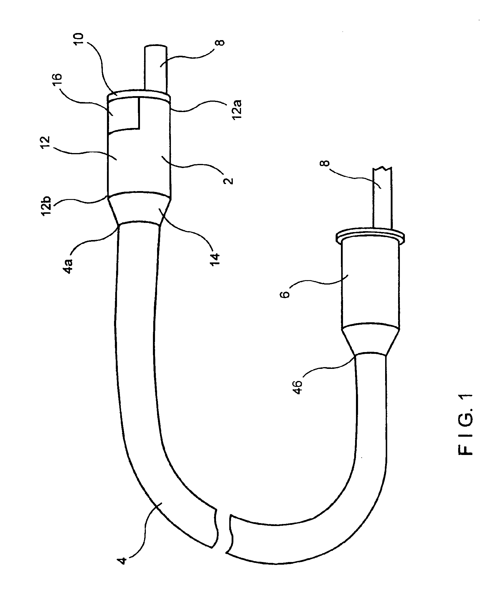
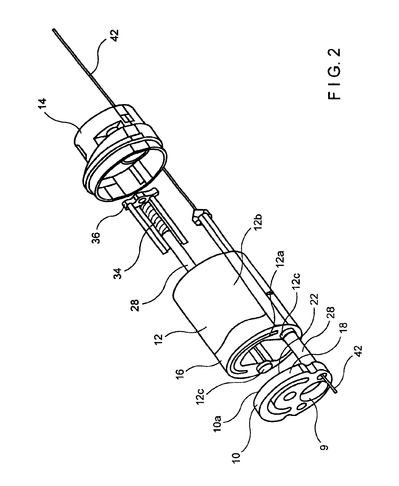
[0018]As shown in FIGS. 1-3, an apparatus according to the present invention comprises a working head assembly 2 which may preferably be connected to a distal end 4a of a sheath 4. The proximal end 4b of the sheath 4 may preferably be connected to a control handle 6 which remains outside the patient's body during operation.

[0019]In operation, the entire apparatus is mounted onto an endoscope 8 by passing the endoscope 8 through the control handle 6, the sheath 4, and through an endoscope receiving channel 9 in the working head assembly 2, as shown in FIGS. 1 and 2. The endoscope 8 is then inserted into an organ via a body orifice to locate a lesion under visual observation (usually while insufflating the organ). The organ may, for example, be a substantially tubular organ such as the colon. Once the lesion has been located, the working head assembly 2 and the sheath 4 are slidably advanced along the endoscope 8 into the organ until the working head assembly 2 is in a desired positio...

second embodiment

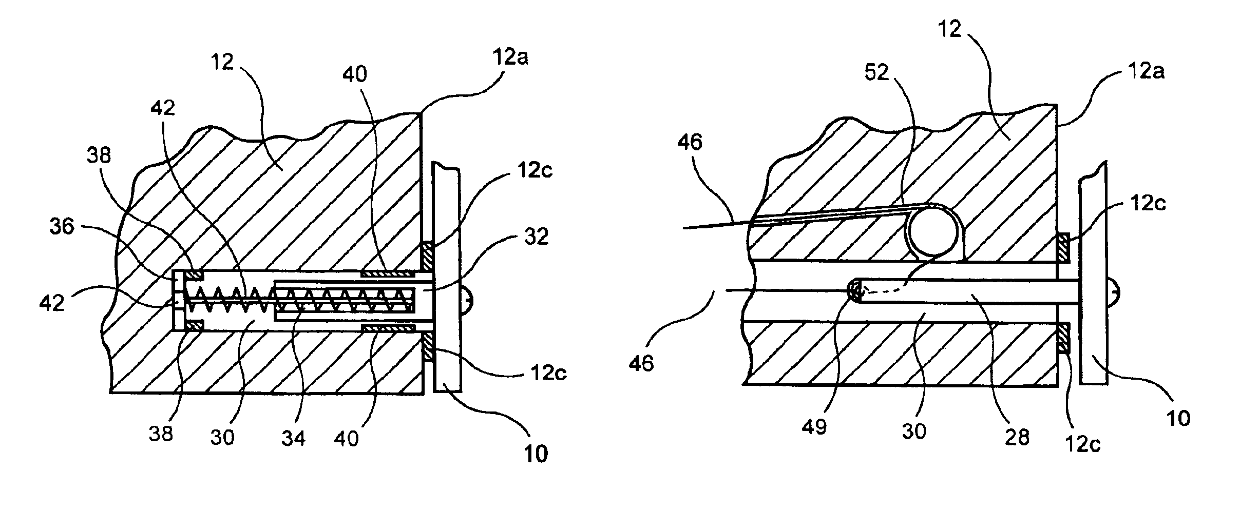
[0027]As shown in FIGS. 4, 5a and 5b, a working head assembly 2′ according to the invention is substantially similar to that of the previously described embodiment except for the drive mechanism which will be described below. The working head assembly 2′ includes an anvil member 10 coupled to the distal end 12a of the working head assembly 2′ by two shafts 28 received into the working head assembly 2′ within corresponding shaft channels 30 as described above in regard to FIGS. 1-3. However, in this embodiment, control cable loops 46 are coupled to the shafts 28, by for example, screws 49 and extend through the sheath 4 to a control cable actuator (not shown) as described above in regard to the control cable 42 of the embodiment shown in FIGS. 1-3. Each of the control cable loops 46 extends from the screw 49, through the corresponding shaft 28, around a pulley 52 back through the working head assembly 2′ and the sheath 4 to the control cable actuator as will be described in more deta...

third embodiment

[0029]As shown in FIG. 6, a working head assembly 2″ according to the invention is substantially similar to the previously described embodiments except for the a drive mechanism for moving the anvil member 10 relative to the distal end 12a of the housing 12. Specifically, the drive mechanism of the working head assembly 2″ includes an axially flexible, substantially torsionally rigid drive shaft 60 including a threaded distal end 60a which engages a mating thread in a channel 64 extending within a first one of the shafts 28′. The first shaft 28′ is coupled to the second of the shafts 28″ by a yoke member 66. The first shaft 28′ is prevented from rotation relative to the housing 12 by, for example, a projection therefrom fitting into a corresponding recess in the respective shaft channel 30. Thus, as the drive shaft 60 is rotated in a first direction relative to the first shaft 28′, the first shaft 28′, the yoke member 66 and the second shaft 28″ are advanced distally into the housin...


PUM

PropertyMeasurementUnit
lengthaaaaaaaaaa
diameteraaaaaaaaaa
thicknessaaaaaaaaaa

Abstract

A full thickness resection device comprises a control handle including an actuator wherein, when the device is in an operative position within a body lumen of a patient, the control handle remains outside the patient's body and a working head assembly coupled to a control handle by a flexible sheath, wherein, when the device is in the operative position; the working head assembly is located within a body lumen of the patient adjacent to a portion of tissue to be treated, the working head assembly including a tissue stapling mechanism including first and second tissue stapling members moveable relative to one another in combination with a first cable extending from the actuator through the flexible sheath to the first tissue stapling member so that, when the actuator is operated to draw the first cable proximally from the sheath, the first tissue stapling member is moved in a first direction relative to the second tissue stapling member.

Description

[0001]The present application is a continuation of a U.S. patent application Ser. No. 10 / 156,293 filed May 24, 2002 now U.S. Pat. No. 6,685,079, entitled “Full Thickness Resectioning Device”.BACKGROUND INFORMATION[0002]Full thickness resection procedures involve excising a full thickness portion of an organ, closing the hole created by the resection and removing the excess tissue.[0003]Several known full thickness resection devices and procedures require at least one incision in an area near a portion of an organ to be excised to allow the physician to access the organ section to be excised and guide the device to that section. Those skilled in the art will understand that these incisions may add substantially to the patient discomfort and recovery time associated with the resectioning procedure itself.SUMMARY OF THE INVENTION[0004]The present invention is directed to a full thickness resection device comprising a control handle including an actuator wherein, when the device is in a...

Claims


Application Information

Patent Timeline
Patent Type & Authority Patents(United States)
IPC IPC(8): A61B17/068A61B17/072A61B17/28A61B17/32A61B17/00A61B17/04A61B17/115
CPCA61B17/07207A61B17/00234A61B17/29A61B17/320016A61B2017/00353A61B2017/07221A61B2017/0725A61B2017/2905
Inventor SHARMA, SATISH K.FREED, DAVID I.PATRONIK, NICHOLASWENDLANDT, JEFFREY M.
Owner BOSTON SCI SCIMED INC
Why Eureka
Try Eureka