Flow control for irrigation machines

a technology of irrigation machine and flow control, which is applied in watering devices, horticulture, agriculture, etc., can solve the problems of unable to meet the needs unable to apply the desired amount of irrigation in the secondary field space, and unable to use the adjustment to address the situation of auxiliary span emitters

Inactive Publication Date: 2005-09-06
LINDSAY CORP
View PDF13 Cites 21 Cited by
  • Summary
  • Abstract
  • Description
  • Claims
  • Application Information

AI Technical Summary

Benefits of technology

[0014]This fluid flow control method utilizing time-based rapid cycling of the flow control apparatus is capable of providing continuously variable average fluid flow as is necessary to meet the changing requirements as the field surface area of responsibility and / or available exposure duration for each emitting device changes.

Problems solved by technology

However, such adjustments cannot be used to address the situation faced by the auxiliary span emitters.
The movements of these emitters create irregularities in both the sizes of their zones of responsibility and the amount of time they spend in those zones.
These irregularities make it difficult to apply the desired amount of irrigation in the secondary field spaces.
That amount may be too much, it may be too little, or perhaps it may even be the desired amount.
Whatever the case may be, the prior art control method can not uniformly vary the average amount of water which is emitted.
As mentioned above, the problem is that both the size of the area of responsibility of a particular emitter and the time available to that emitter in which it can apply water to that area are constantly changing.
The prior art control methods and apparatus are incapable of adequately dealing with these variations.

Method used


Image

  • Flow control for irrigation machines
  • Flow control for irrigation machines
  • Flow control for irrigation machines

Examples


Embodiment Construction

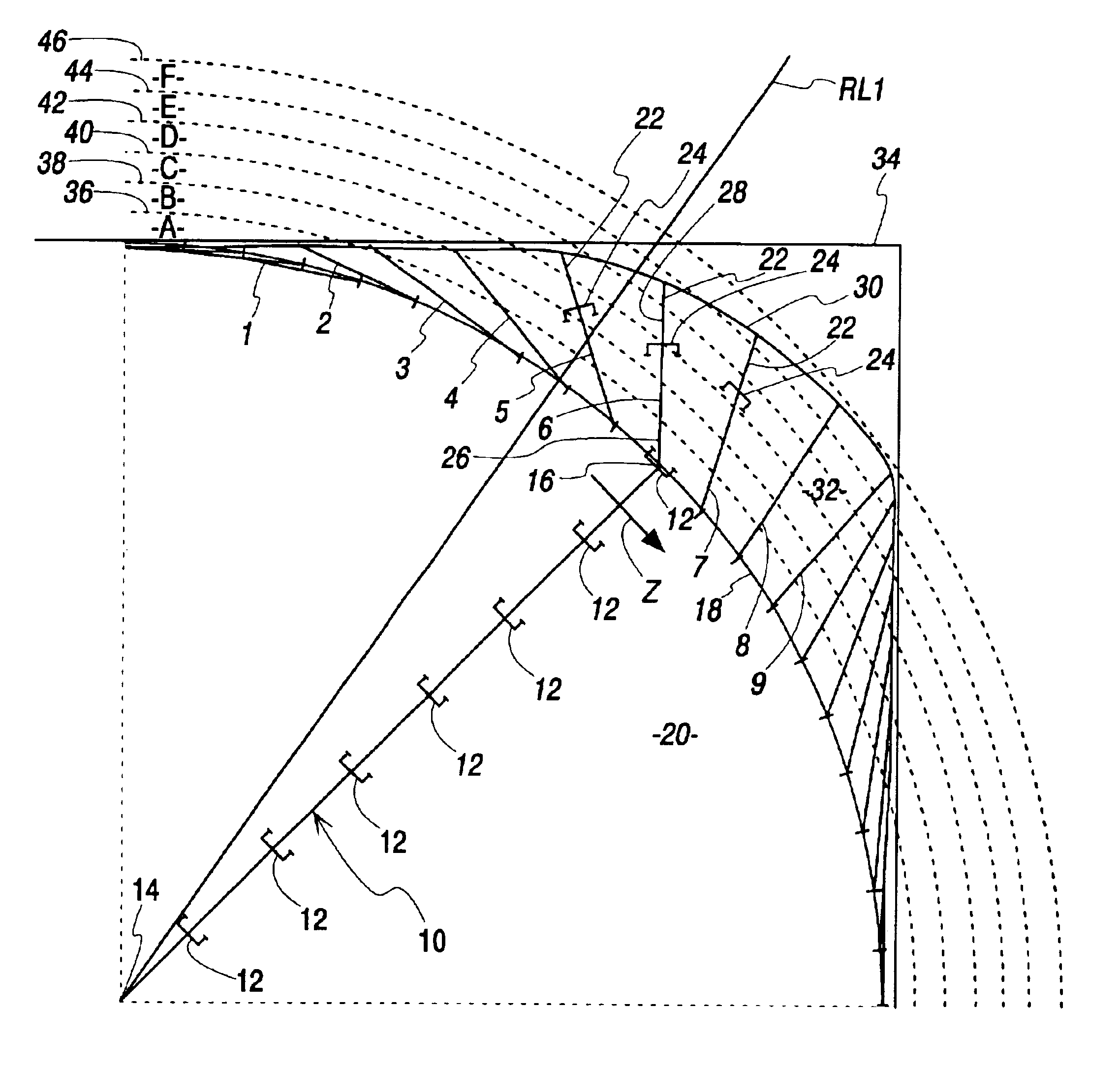
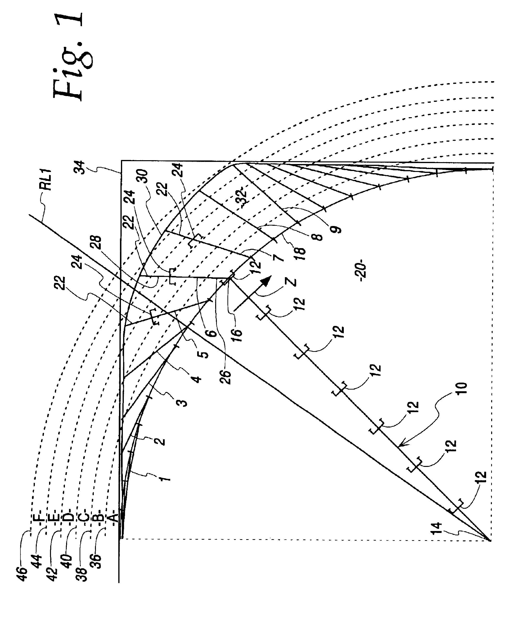
[0020]FIG. 1 schematically illustrates a center pivot irrigation machine according to the present invention. The machine includes a main pipeline 10 mounted on self-propelled towers 12. The inner end 14 of the main pipeline is mechanically connected to a center pivot. Irrigation fluid, which may be water or water mixed with fertilizer, herbicide, insecticide or the like is supplied to the main pipeline at the center pivot. The outer end 16 of the main pipeline describes a circle 18 as it moves in the direction of arrow Z. The circle 18 defines the primary field space 20. Emitters (not shown) are located along the main pipeline for distributing fluid to the primary field space.

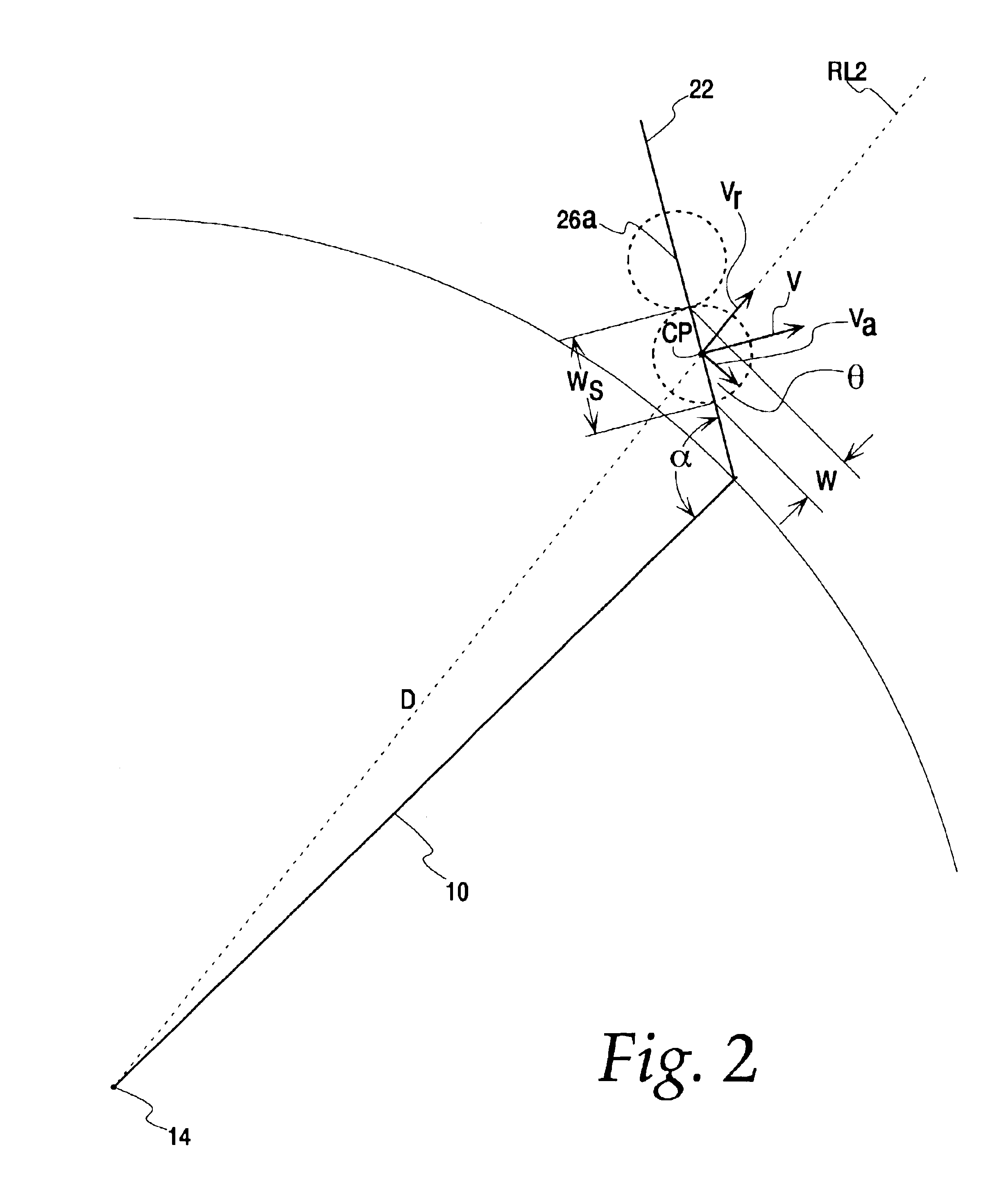
[0021]An auxiliary span 22 is mounted on an auxiliary tower 24 and connected near an outer end 16 of the main pipeline. The auxiliary span is a pipeline that receives fluid from the main pipeline for distribution through a plurality of auxiliary emitters spaced along the auxiliary span. Two such emitters are sh...


PUM


Abstract

This invention relates to a fluid flow control method that enables a self-propelled irrigation machine to apply varying amounts of fluid as might be required to suitably treat the surface area affected by each of the individual fluid application devices thereon. The control method regulates the total volume of fluid emitted by each application device to a predetermined value as it responds to a suitable control signal to permit or prevent fluid flow. This fluid flow control method involves time-based rapid cycling of the flow control apparatus to provide continuously variable fluid flow as is required to meet the desired average output of each emitting device as the flow requirement varies from time to time as needed to produce a selected, pre-determined application rate throughout the treated surface area.

Description

BACKGROUND OF THE INVENTION[0001]Agricultural irrigation machines of the type known as center pivot machines have a main pipeline section supported at intervals on movable towers for rotation about an inner end of the pipeline. Water is supplied to the fixed, inner end of the pipeline and distributed through sprinklers or other fluid emitting devices placed along or supported from the pipeline. The movement of the main pipeline section about its central pivot point irrigates a circular portion of a field. The circular portion swept by the main pipeline is designated herein the primary field space. This leaves the corners of square or rectangular fields or other irregular perimeter areas without irrigation. In installations where the additional productive capacity of a field's corners or irregular perimeter areas warrants, the corners or irregular perimeter areas can be irrigated by adding an auxiliary span or spans near the outer end of the main pipeline for irrigating areas of the ...

Claims


Application Information

Patent Timeline
Patent Type & Authority Patents(United States)
IPC IPC(8): A01G25/09A01G25/00
CPCA01G25/092
Inventor CHOAT, WAYNE D.CALLIES, ROBERT E.
Owner LINDSAY CORP
Why Eureka
Try Eureka