Universal bus bar connector with multi-pitch threaded hole

a universal bus bar and threaded hole technology, applied in the direction of transformer/coil connectors, coupling device connections, electrical devices, etc., can solve the problems of exacerbated problems, and adding complexity and expense to the manufacturing process

Active Publication Date: 2005-09-06
THOMAS & BETTS INT INC
View PDF12 Cites 41 Cited by
  • Summary
  • Abstract
  • Description
  • Claims
  • Application Information

AI Technical Summary

Benefits of technology

[0012]The present invention therefore provides a connector for attachment to an extending transformer stud. The connector includes an elongate central body having a longitudinal bore, opening at one end for insertable accommodation of the transformer stud. The longitudinal bore accepts more than one size stud without increasing the size and cost needed for two separate mounting holes. The connector according to the present invention accepts the pitch of at least two different size threads and with the typical setscrew locking arrangement, maintains thread engagement on one side of the stud, securing the stud and maintaining electrical contact area between the stud and the connector.
[0014]The present invention uses a single hole or bore within the body of a connector to accept two or more threaded studs of different thread sizes. This is accomplished in the present invention by using the principle of superposition (overlaying) of the desired threads and pitches to provide for a resulting threaded section, which allows two different size threaded studs to be firmly interlocked within the threaded hole. In other words, the present invention provides for partial or complete thread distortion on a pre-existing thread by removal of thread sections, which correspond to the size, and pitch of a second thread.

Problems solved by technology

However, the disadvantage of such design is that it requires at least two holes, and therefore needs to be larger than necessary.
Also, because by design the stud hole has to meet a certain depth to accommodate the stud, the portion of the connector receiving the threaded stud in not usable for conductor connections, thus additionally requiring a longer connector to accommodate an equal number of conductors.
This problem is exacerbated for connectors having multiple threaded holes.
The disadvantage of this design is that it requires pre-drilling a smaller hole, followed by drilling of the second larger hole, partially overlapping the smaller hole.
Both methods therefore require a two-step process, which adds complexity and expense to the manufacturing process.
However, this design requires a second element, the slider, to be added to the connector, which adds complexity and expense to the manufacturing process.

Method used


Image

  • Universal bus bar connector with multi-pitch threaded hole
  • Universal bus bar connector with multi-pitch threaded hole
  • Universal bus bar connector with multi-pitch threaded hole

Examples


Embodiment Construction

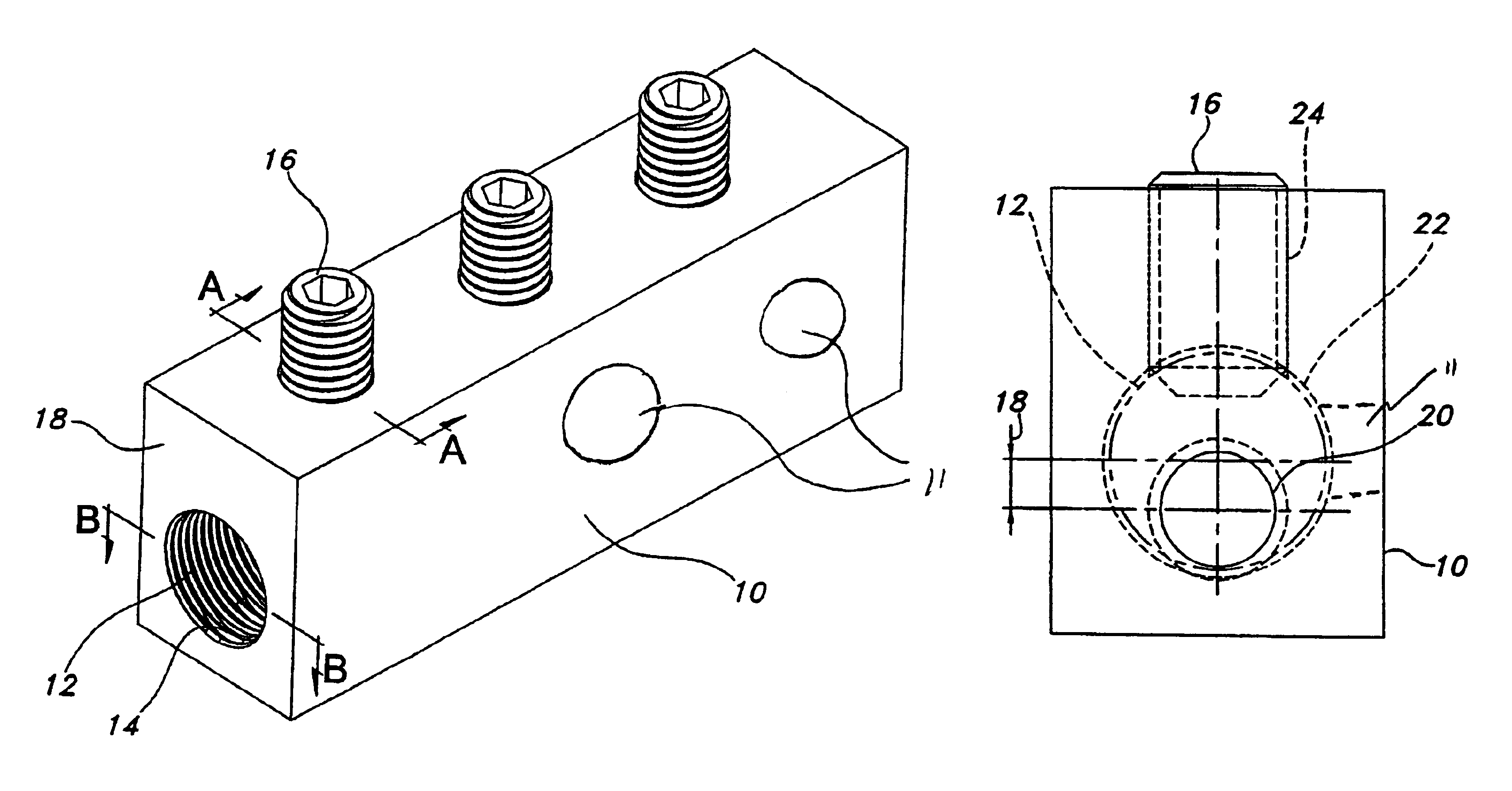
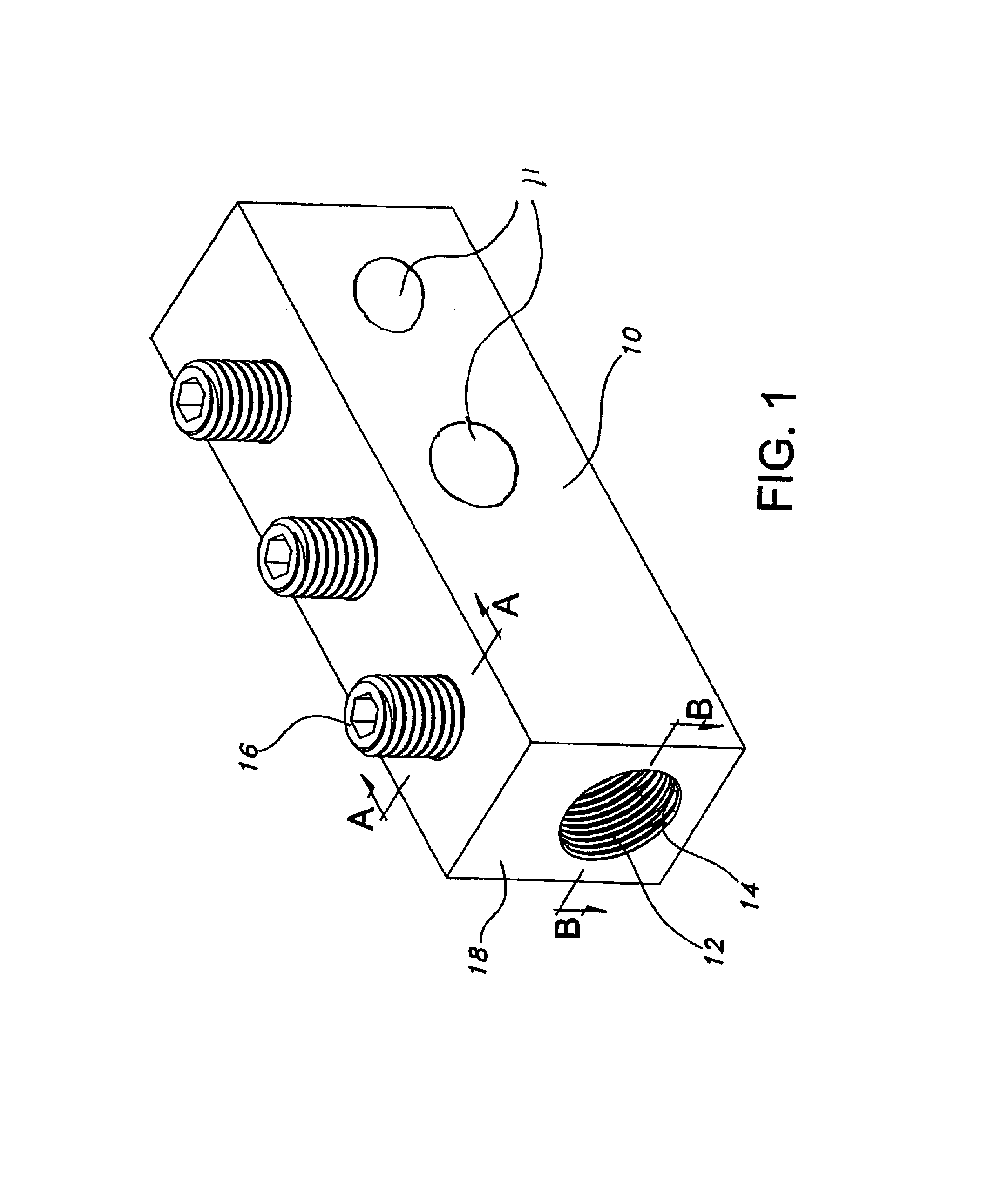
[0023]Referring to FIG. 1, there is shown a perspective view of the connector according to the present invention. Shown is connector body 10, longitudinal bore 12, having threads 14 disposed along the inner diameter, and set screws 16, protruding from the top of connector body 10 and which can be screwed into connector body 10 to contact transformer stud (not shown). There is further shown side surface 18 of the connector body, which, when mounted to a transformer stud faces the transformer. The connector body 10 is an integrally formed metallic member, preferably formed of aluminum or other material, having high electrical conductivity. Transformer stud connector body 10 includes central, generally elongate cylindrical bore 12. The central bore 12 is internally threaded to accommodate the extending, externally threaded transformer stud (not shown). The length of bore 12 need only be approximately the length of the extending portion of the stud so that when the body is placed over t...


PUM


Abstract

A connector is attachable to an extending transformer stud. The connector includes an elongate central body having a longitudinal bore opening at one end for insertable accommodation of the transformer stud. The longitudinal bore accepts more than one size stud without increasing the size and cost needed for two separate mounting holes. The connector according to the present invention accepts the pitch of at least two different size threads and with the typical setscrew locking arrangement, maintains thread engagement on one side of the stud, securing the stud and maintaining an electrical contact area between the stud and the connector.

Description

CROSS-REFERENCE TO RELATED APPLICATIONS[0001]This application claims priority to U.S. Provisional Application No. 60 / 486,318, filed Jul. 11, 2003.FIELD OF THE INVENTION[0002]The present invention relates generally to a connector for connecting to a transformer having a single stud hole with superimposed multiple threads. More particularly, the present invention relates to a transformer stud connector, having a single threaded hole, which permits the connector to install studs of different sizes.BACKGROUND OF THE INVENTION[0003]Electrical transformers are typically used to distribute electrical power from main utility lines for secondary distribution. The transformer accepts the main utility line on the primary side of the transformer and distributes the power from a secondary side of the transformer. An electrical step-down is provided by the transformer so as to provide for the proper secondary distribution of electrical power for residential and commercial use.[0004]The transforme...

Claims


Application Information

Patent Timeline
Patent Type & Authority Patents(United States)
IPC IPC(8): H01R4/36H01R31/02H01R4/28H01R31/00H01R4/30
CPCH01R4/36H01R31/02H01R4/307H01R2201/22Y10S439/921
Inventor FERRETTI, MICHAEL JOHNTRIANTOPOULOS, GEORGE
Owner THOMAS & BETTS INT INC
Why Eureka
Try Eureka