Power supply unit and image forming device having the same

a technology of power supply unit and image forming device, which is applied in the direction of emergency protective arrangement for limiting excess voltage/current, relays, instruments, etc., can solve the problems of hammering down the size internal components to which high voltage is supplied, and achieve the effect of not increasing the size and cost of the power supply uni

Active Publication Date: 2013-08-06
BROTHER KOGYO KK
View PDF23 Cites 12 Cited by
  • Summary
  • Abstract
  • Description
  • Claims
  • Application Information

AI Technical Summary

Benefits of technology

[0008]Aspects of the present invention are advantageous in that at least one of a power supply unit and an image forming device having the same configured such that when anomalous high voltage output occurs, high voltage output can be stopped while suppressing deterioration of components due to an anomalous state of the high voltage output, without increasing the size of the power supply unit is provided.
[0010]Such a configuration makes it possible to stop output of the high voltage in accordance with detection of the anomalous state without increasing the size and cost of the power supply unit.
[0012]Such a configuration makes it possible to stop output of the high voltage in accordance with detection of the anomalous state without increasing the size and cost of the power supply unit.

Problems solved by technology

However, use of such an interlock switch hampers downsizing of the power supply unit.
In this case, internal components to which high voltages are supplied might be damaged.

Method used


Image

  • Power supply unit and image forming device having the same
  • Power supply unit and image forming device having the same
  • Power supply unit and image forming device having the same

Examples


first embodiment

[0022

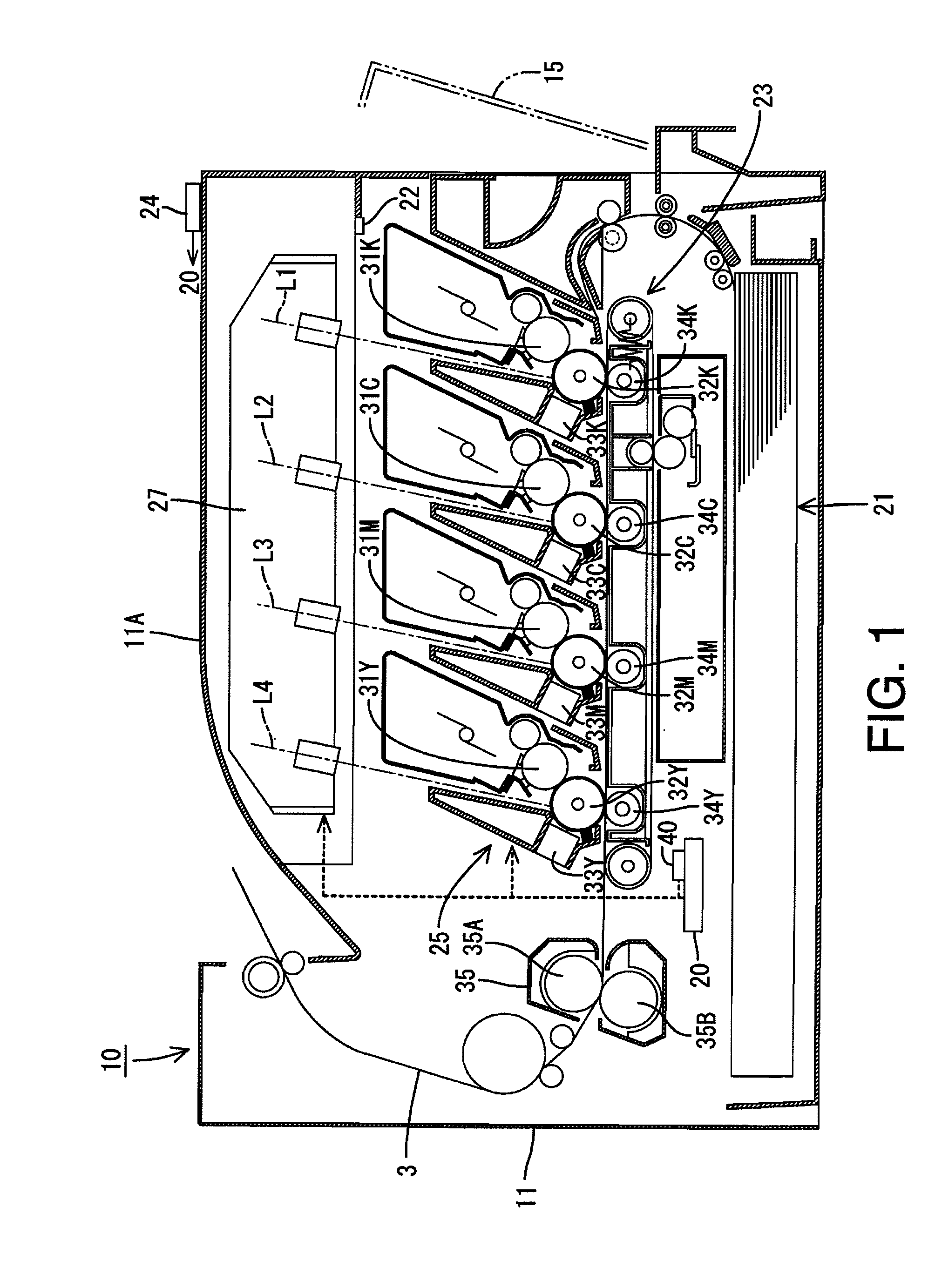
[0023]FIG. 1 is a cross section illustrating a general configuration of a laser printer 10 according to a first embodiment.

[0024]The laser printer 10 is a so-called direct tandem type color laser printer. That is, the laser printer 10 includes four development rollers 31K, 31C, 31M and 31Y respectively corresponding to four colors of black, cyan, magenta and yellow, and four photosensitive drums 32K, 32C, 32M and 32Y respectively corresponding to four colors of black, cyan, magenta and yellow. In the following, the right side on FIG. 1 is defined as a front side of the laser printer 1. It should be noted that various types of image forming devices, such as a monochrome laser printer, an LED printer and a multifunction peripheral having facsimile and copy functions, can be employed as a device to which the feature of an embodiment is applied.

[0025]The laser printer 10 (hereafter, simply referred to as a printer 10) has a box-shaped body casing 11. In the body casing 11, a paper ...

second embodiment

[0051

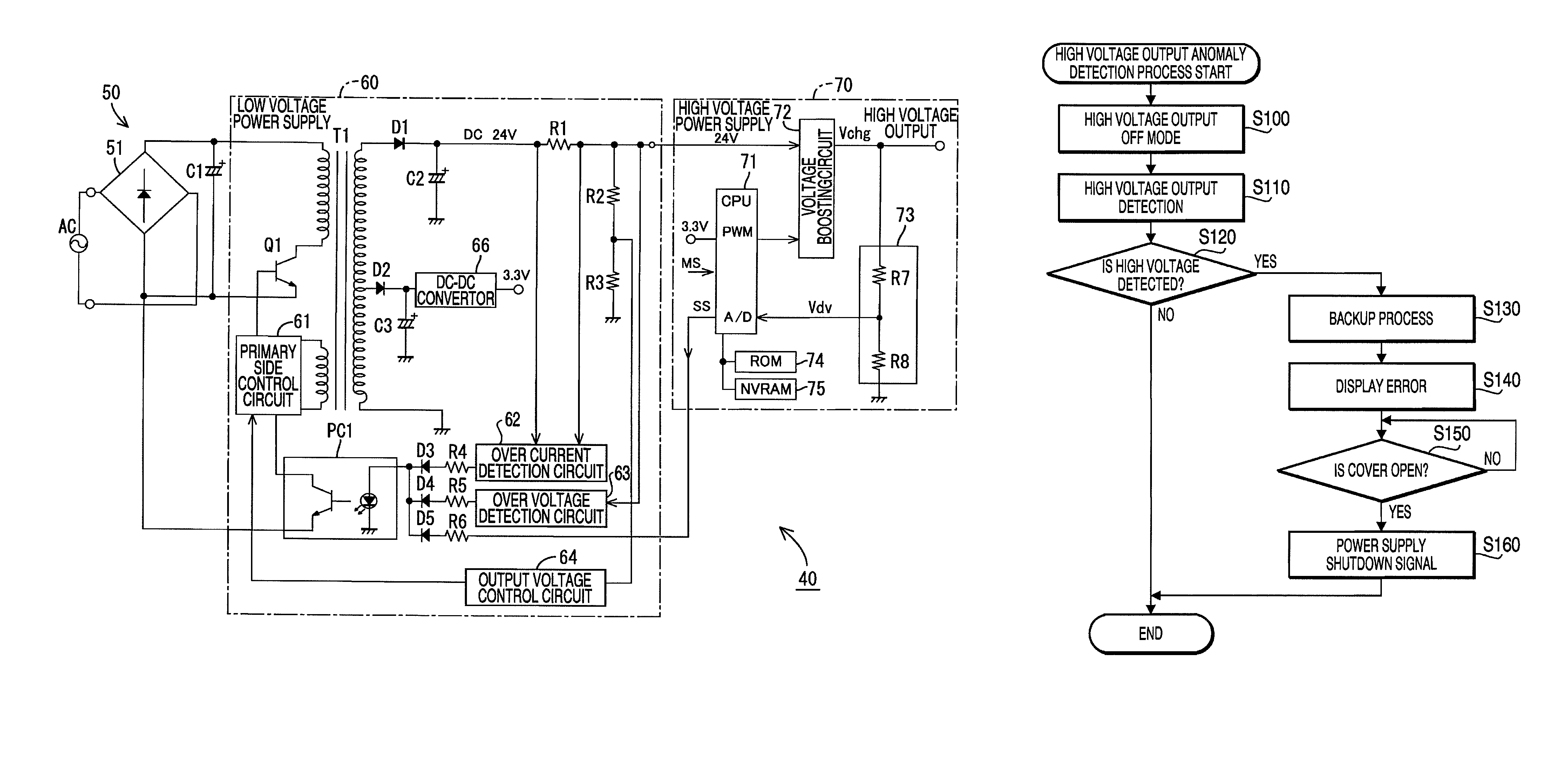
[0052]Hereafter, a second embodiment is described with reference to FIGS. 5 and 6. Since the feature of the second embodiment corresponds to a variation of the power supply unit of the first embodiment, in the following the explanations focus on the feature of the second embodiment. Therefore, in the following, the same reference numbers as those of the first embodiment are also referred to for the explanation of the second embodiment.

[0053]FIG. 5 is a circuit diagram of a power supply unit 40A according to the second embodiment. As shown in FIG. 5, the power supply unit 40A includes two low voltage power supply units 60A and 60B. The low voltage power supply unit 60B generates DC 3.3.V. Therefore, in this embodiment, the low voltage power supply unit 60A is configured such that the diode D2 and the capacitor C3 and the DC-DC converter 66 are omitted from the low voltage power supply unit 60 of the first embodiment.

[0054]Similarly to the low voltage power supply unit 60A, the l...


PUM


Abstract

There is provided a power supply unit, comprising: a converter transformer; a first low voltage generation unit to generate a first voltage on a secondary side of the converter transformer and output the first voltage; a first controller that controls an activation state of a primary side of the converter transformer based on the first voltage; an inactivation unit to inactivate operation of the first controller based on the first voltage to let the first low voltage generation unit to suspend output of the first voltage; a high voltage supply unit to output a high voltage higher than the first voltage by using the first voltage; a detection unit to detect an anomalous state concerning output of the high voltage of the high voltage supply unit. The high voltage supply unit inactivates the operation of the first controller through the inactivation unit when the anomalous state is detected.

Description

CROSS-REFERENCE TO RELATED APPLICATION[0001]This application claims priority under 35 U.S.C. §119 from Japanese Patent Application No. 2008-222045, filed on Aug. 29, 2008. The entire subject matter of the application is incorporated herein by reference.BACKGROUND[0002]1. Technical Field[0003]Aspects of the present invention relate to a power supply unit and an image forming device having the power supply unit.[0004]2. Related Art[0005]In general, a power supply unit is provided in an image forming device to supply voltages to components in the image forming device. Japanese Patent Provisional Publication No. 2001-086742A discloses a technique in which a voltage is outputted on a secondary side of a converter transformer, and switching control is performed for controlling an activation state of a primary side of the converter transformer based on an output voltage on the primary side of the converter transformer.[0006]Regarding an image forming device having a cover through which a u...

Claims


Application Information

Patent Timeline
Patent Type & Authority Patents(United States)
IPC IPC(8): G03G15/00
CPCG03G15/5004H02M1/32H02M1/36
Inventor INUKAI, KATSUMI
Owner BROTHER KOGYO KK
Why Eureka
Try Eureka