
Light guide element and image display apparatus

a technology of light guide elements and image display apparatuses, applied in the direction of optics, instruments, optical light guides, etc., can solve the problems of image sharpness deterioration and image cannot be partially seen

Pending Publication Date: 2022-10-13
FUJIFILM CORP
View PDF0 Cites 0 Cited by
  • Summary
  • Abstract
  • Description
  • Claims
  • Application Information

AI Technical Summary

Benefits of technology

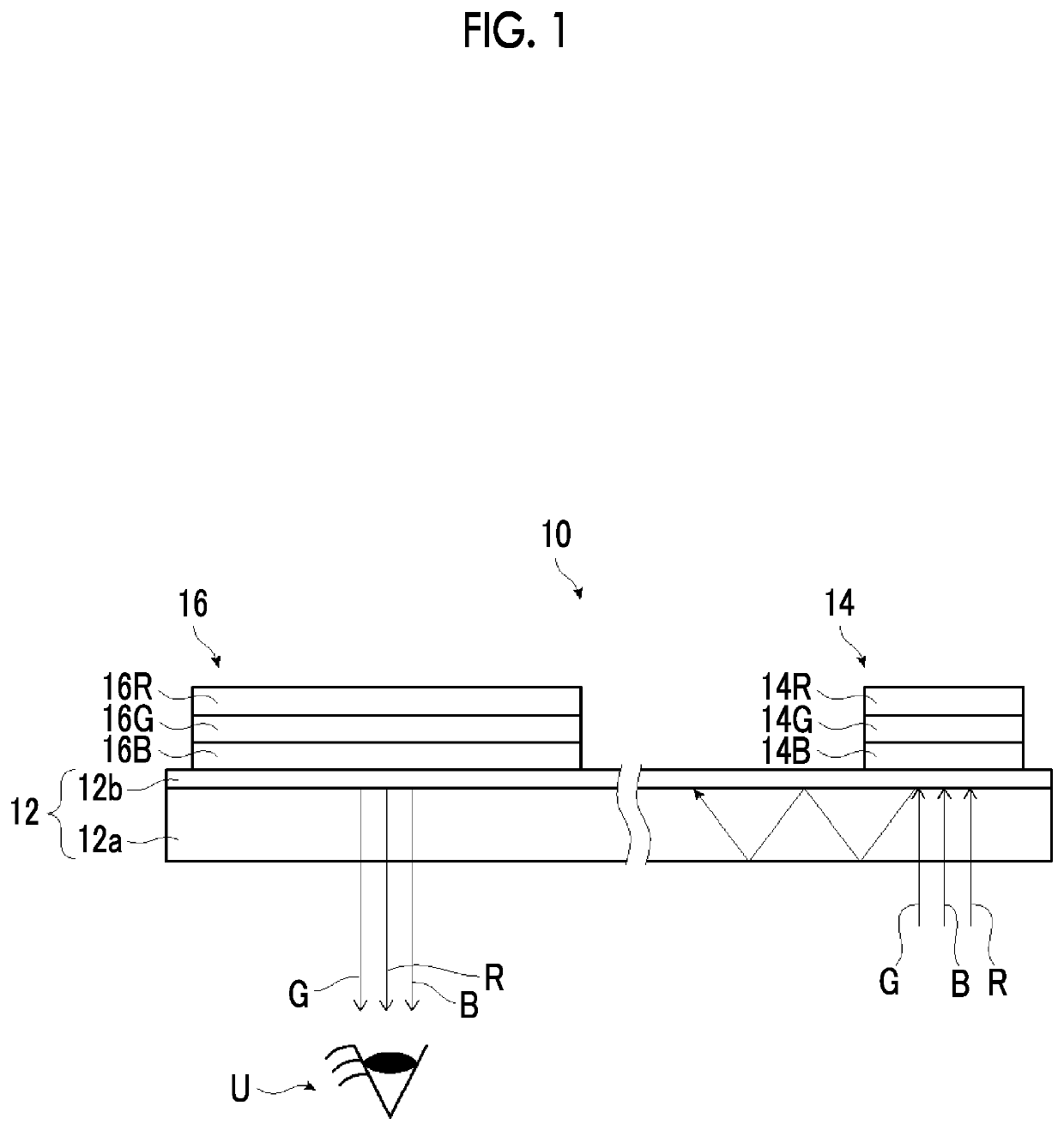
The invention provides a light guide element and an image display apparatus that can prevent deterioration in image sharpness and allow for suitable observation of the entire display image regardless of the user's eyesight or viewing angle. This results in improved image quality and a more engaging viewing experience for the user.

Problems solved by technology

However, according to an investigation by the present inventors, it was found that, in an image display apparatus in the related art including a light guide plate, for example, in AR glasses, in a case where a user moves the visual line or moves the position of eyes, the image cannot be partially seen, that is, so-called deterioration in image sharpness occur, and there may be a case where an appropriate image cannot be observed.

Method used


Image

  • Light guide element and image display apparatus
  • Light guide element and image display apparatus
  • Light guide element and image display apparatus

Examples


example 1

[0370](Formation of Alignment Film)

[0371]A glass substrate was used as the support.

[0372]The following coating liquid for forming an alignment film was applied to the support by spin coating. The support on which the coating film of the coating liquid for forming an alignment film was formed was dried using a hot plate at 60° C. for 60 seconds. As a result, an alignment film P-1 was formed.

[0373]Coating Liquid for Forming Alignment Film

The following material for photo-alignment1.00 part by massWater16.00 parts by massButoxyethanol42.00 parts by massPropylene glycol monomethyl ether42.00 parts by mass

[0374]—Material for Photo-Alignment—

[0375](Exposure of Alignment Film)

[0376]The alignment film was exposed using the exposure device shown in FIG. 8 to form an alignment film P-1 having an alignment pattern.

[0377]In the exposure device, a laser that emits laser light having a wavelength (325 nm) was used as the laser. The exposure amount of the interference light was 300 mJ / cm2. The sing...

example 2

[0398]A light guide element was prepared using the same method as that of Example 1, except that the glass plate of the second light guide layer was changed to a glass plate having a refractive index of 1.7 to prepare a light guide plate.

example 31

[0399]A light guide element was prepared using the same method as that of Example 1, except that the thickness of the first light guide layer was changed to 0.7 mm and the thickness of the second light guide layer was changed to 0.3 mm to prepare a light guide plate.


PUM

PropertyMeasurementUnit
wavelength rangeaaaaaaaaaa

Abstract

Provided are: a light guide element in which deterioration in image sharpness can be prevented and the entire area of a display image can be suitably observed irrespective of the visual line of a user, the position of eyes of the user, and the like; and an image display apparatus including the light guide element. The light guide element includes: a light guide plate that includes a first light guide layer and a second light guide layer; and an incidence diffraction element and an emission diffraction element that are laminated on the second light guide layer, in which in a case where a refractive index of the first light guide layer is represented by n1 and a refractive index of the second light guide layer is represented by n2 in the light guide plate, n1<n2 is satisfied.

Description

CROSS-REFERENCE TO RELATED APPLICATIONS[0001]This application is a Continuation of PCT International Application No. PCT / JP2020 / 047505 filed on Dec. 18, 2020, which claims priority under 35 U.S.C. § 119(a) to Japanese Patent Application No. 2019-239151 filed on Dec. 27, 2019. The above application is hereby expressly incorporated by reference, in its entirety, into the present application.BACKGROUND OF THE INVENTION1. Field of the Invention[0002]The present invention relates to a light guide element where light is incident, propagates, and is emitted, and an image display apparatus that includes the light guide element.2. Description of the Related Art[0003]Recently, as described in Bernard C. Kress et al., Towards the Ultimate Mixed Reality Experience: HoloLens Display Architecture Choices. SID 2017 DIGEST, pp. 127-131, augmented reality (AR) glasses that display a virtual image and various information or the like to be superimposed on a scene that is actually being seen have been ...

Claims


Application Information

Patent Timeline
Patent Type & Authority Applications(United States)
IPC IPC(8): G02B27/01F21V8/00
CPCG02B27/0172G02B6/0016G02B6/0035G02B6/0056G02B2027/0112G02B2027/0178G02B5/18G02B5/32G02B27/4205G02B27/4261G02B5/3016
Inventor SATO, HIROSHISASATA, KATSUMISAITOH, YUKITO
Owner FUJIFILM CORP
Learn More