
Turbocharger

a technology of turbocharger and cylinder head, which is applied in the direction of internal combustion piston engines, machines/engines, combustion engines, etc., can solve the problems of an increase in the number of components, the proportion in contact with the waved washer is easy to be worn away, and the component deterioration is earlier, so as to suppress the deterioration of components and reduce the number of components. , the effect of strong sealing for

Inactive Publication Date: 2016-04-12
OTICS CORP
View PDF11 Cites 0 Cited by
  • Summary
  • Abstract
  • Description
  • Claims
  • Application Information

AI Technical Summary

Benefits of technology

[0010]The present invention is accomplished in view of the foregoing problems, and aims to provide a turbocharger that prevents a seizure of a shaft member, prevents a leakage of exhaust gas, suppresses deterioration of components, and reduces a number of components.
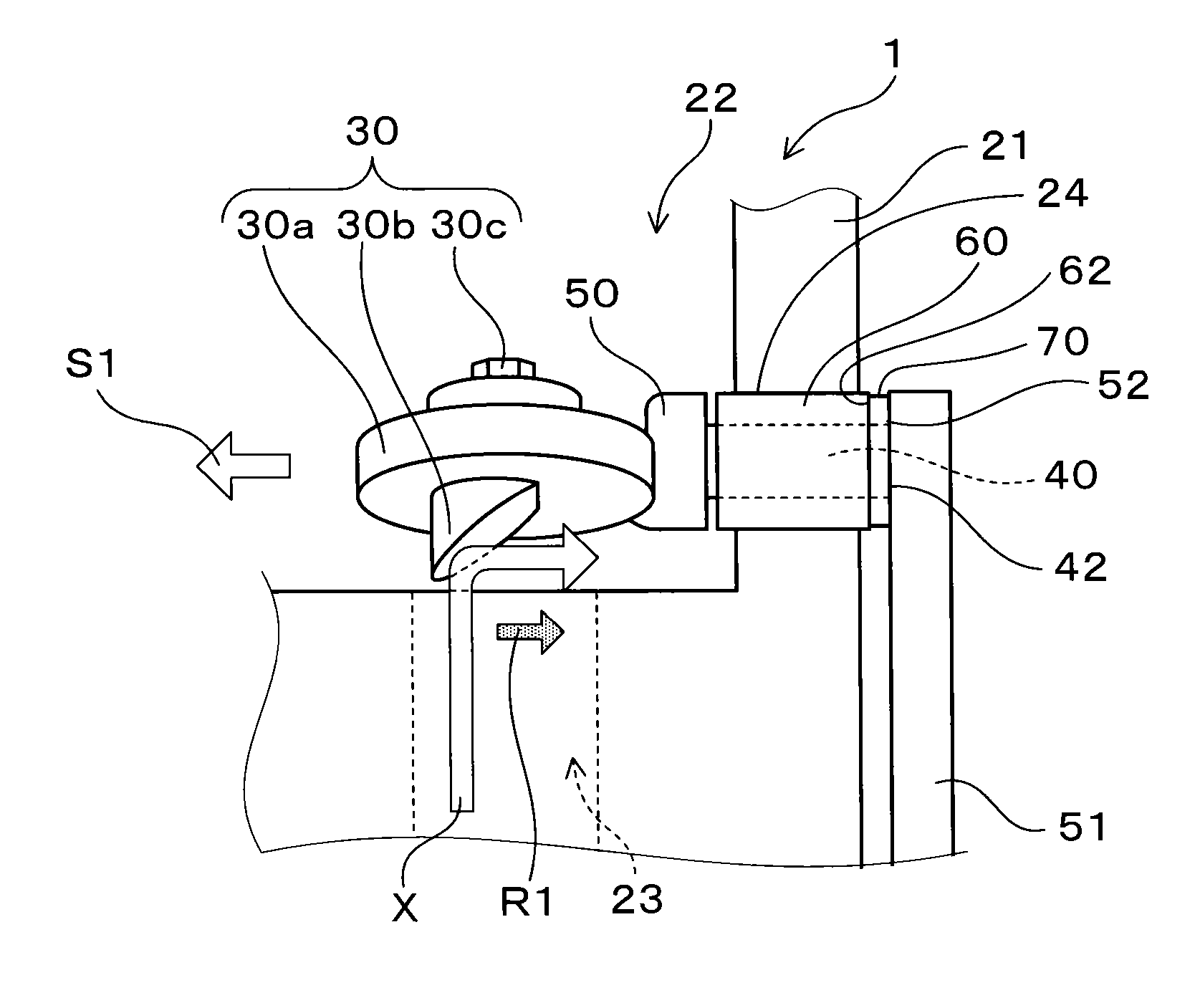
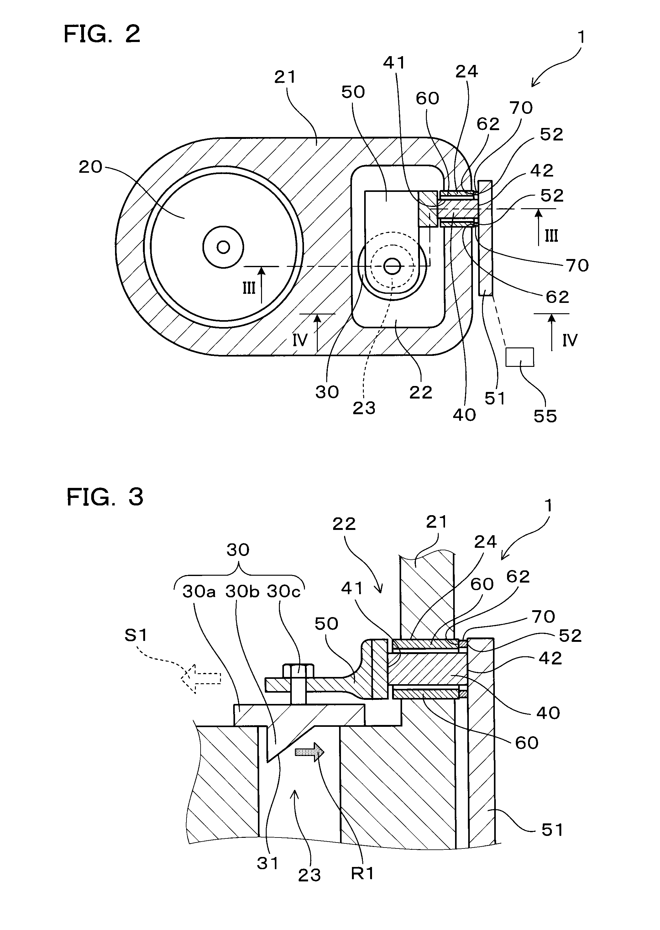
[0021]The thrust force allows the seal contact portion to press against the peripheral edge of the support hole via the seal member, whereby strong sealing force is generated between both of them. As a result, the leakage of the exhaust gas from the gap between the support hole and the shaft member can be prevented. Since the gap can be secured between the support hole and the shaft member, the seizure of the shaft member can be prevented.
[0024]Instead, the merits described below are obtained. The turbocharger generates strong sealing force based upon the thrust force, when strong sealing force is needed, i.e., when the gas pressure in the turbine housing is high. On the other hand, when strong sealing force is not needed, i.e., when the gas pressure in the turbine housing is low, the turbocharger does not generate the strong sealing force. This structure brings a merit of suppressing the deterioration of the components such as the seal member, compared to the case where the sealing is attained by the constant sealing force at all times. In addition, a separate member such as a waved washer for causing the strong sealing force is not needed, whereby the number of components can be reduced.
[0025]As described above, the present invention can provide a turbocharger that prevents a seizure of a shaft member, prevents a leakage of exhaust gas, suppresses deterioration of components, and reduces a number of components.

Problems solved by technology

However, in the configuration described in Patent Document 1, the seal member is always pressed by the waved washer serving as the biasing member, so that there arise problems that the portion in contact with the waved washer is easy to be worn away, and the components is deteriorated earlier.
The configuration described above needs the biasing member such as the waved washer for obtaining pressure force, thereby entailing a problem of an increase in the number of components.

Method used


Image

  • Turbocharger
  • Turbocharger
  • Turbocharger

Examples


embodiment 1

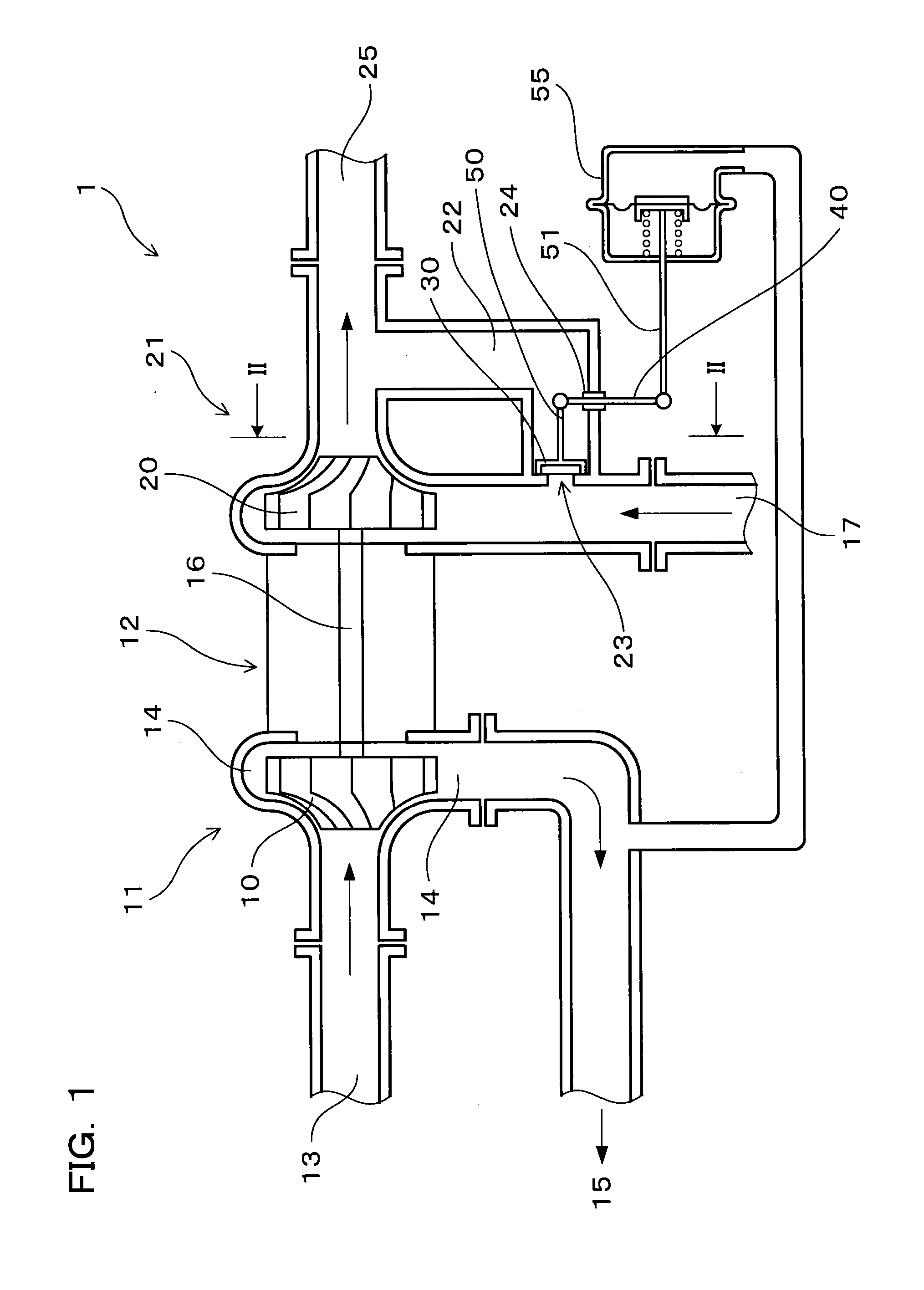
[0045]An embodiment of the turbocharger will be described with reference to FIGS. 1 to 4.

[0046]As illustrated in FIG. 1, a turbocharger 1 according to the present embodiment includes a turbine impeller 20 connected to a compressor impeller 10, a turbine housing 21 storing the turbine impeller 20, and a bypass passage 22 that is connected an upstream space and a downstream space of the turbine impeller 20 in the turbine housing 21 for bypassing the turbine impeller 20. A flow rate of gas supplied to the turbine impeller 20 is adjusted by opening or closing an opening 23 of the bypass passage 22.

[0047]As illustrated in FIGS. 1 and 2, the turbocharger 1 also includes a waste gate valve 30, a shaft member 40, an inner coupling member 50, and an outer coupling member 51.

[0048]The waste gate valve 30 is provided to the opening 23 so as to be capable of being opened and closed. The shaft member 40 is rotatably supported by being inserted into a support hole 24 penetrating the turbine housi...

embodiment 2

[0080]As illustrated in FIGS. 8 and 9, a turbocharger 100 according to the present embodiment includes a waste gate valve 300 instead of the waste gate valve 30 and a seal member 702 instead of the seal member 70 in the turbocharger 1 according to the embodiment 1. An end part of the bush member 60 protruding to the inside of the turbine housing 21 forms a peripheral edge 622 of the support hole 24. The components same as those in the embodiment 1 are identified by the same numerals, and the redundant description will not be repeated.

[0081]In the turbocharger 100 according to the present embodiment, a seal contact portion 520 is located on the inner coupling member 50 along the peripheral edge 622 of the support hole 24, the inner coupling member 50 facing the peripheral edge 622, as illustrated in FIG. 8. The seal member 702 is provided between the seal contact portion 520 and the peripheral edge 622.

[0082]As illustrated in FIG. 8, the waste gate valve 300 has a projecting portion ...


PUM


Abstract

The present invention provides a turbocharger that prevents a seizure of a shaft member, prevents a leakage of exhaust gas, suppresses deterioration of components, and reduces a number of components. The turbocharger includes a waste gate valve which is connected to the shaft member rotatably supported by penetrating a support hole of the turbine housing. The waste gate valve includes an inclined surface formed at a portion facing an opening of a bypass passage. When the waste gate valve is opened, exhaust gas flown into the bypass passage presses the inclined surface, thrust force is applied to the shaft member in a shaft direction, and a seal contact portion is pressed against a peripheral edge of the support hole via a seal member.

Description

CROSS-REFERENCE[0001]This application claims priority to Japanese patent application no. 2013-068474 filed on Mar. 28, 2013, the contents of which are entirely incorporated herein by reference.BACKGROUND OF THE INVENTION[0002]1. Field of the Invention[0003]The present invention relates to a turbocharger including a turbine housing.[0004]2. Description of Related Art[0005]A turbocharger mounted to a vehicle or the like is configured to compress air, which is sucked by forcibly rotating a compressor impeller by the rotation of a turbine impeller connected to the compressor impeller by exhaust gas, and to exhaust the compressed air toward an internal combustion engine. The turbocharger is also provided with a bypass passage connected to an upstream side and a downstream side of the turbine impeller for allowing the flown exhaust gas to bypass the turbine impeller, and a waste gate valve that opens and closes an opening of the bypass passage.[0006]The waste gate valve is configured to c...

Claims


Application Information

Patent Timeline
Patent Type & Authority Patents(United States)
IPC IPC(8): F02B37/18
CPCF02B37/183F02B37/186Y02T10/144Y02T10/12
Inventor ISOGAI, TOMOYUKI
Owner OTICS CORP
Learn More