Charge/discharge system

a technology of discharge system and discharge device, which is applied in the direction of electric devices, battery/fuel cell control arrangement, electric devices, etc., can solve the problems of wasting electric power and accelerating parts degradation, and achieve the effect of suppressing parts degradation and reducing power consumption

Active Publication Date: 2016-05-24
MITSUBISHI ELECTRIC CORP
View PDF21 Cites 0 Cited by
  • Summary
  • Abstract
  • Description
  • Claims
  • Application Information

AI Technical Summary

Benefits of technology

[0009]It is an object of the present invention to provide a charge / discharge system capable of reducing power consumption and suppressing degradation of parts even when the system is connected to a smart grid for a long time.
[0011]Since the charge / discharge system of the present invention includes the power supply unit for controlling power supply to supply power only to a unit contributing charge / discharge when charge / discharge to / from the battery from / to the outside of the vehicle is performed, it is possible to reduce power consumption and suppress degradation of parts even when the system is connected to a smart grid for a long time.

Problems solved by technology

This arises problems of wasting the electric power and accelerating degradation of parts.

Method used


Image

  • Charge/discharge system
  • Charge/discharge system
  • Charge/discharge system

Examples


Embodiment Construction

The Preferred Embodiment

[0022]

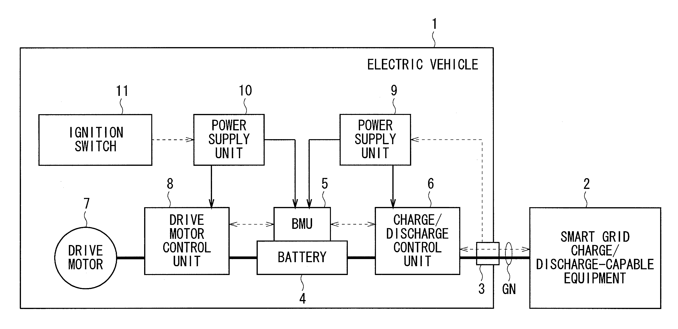
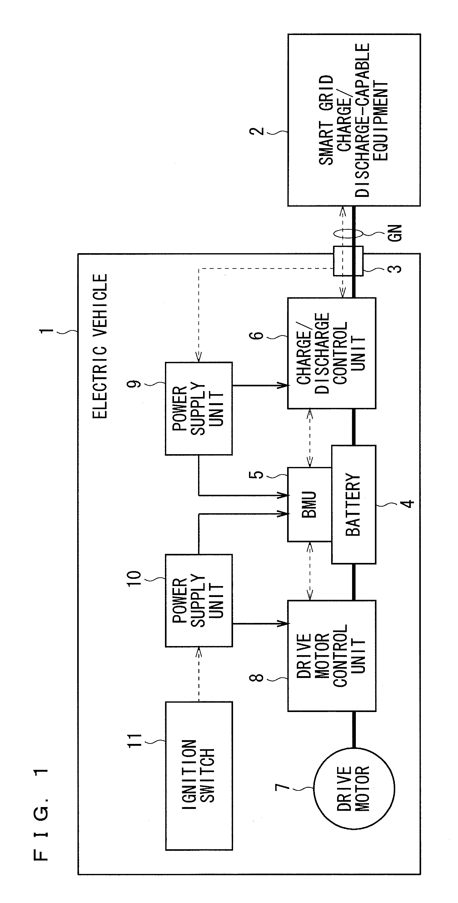
[0023]FIG. 1 is a block diagram showing a constitution of an electric vehicle 1 comprising a charge / discharge system in accordance with a preferred embodiment of the present invention.

[0024]As shown in FIG. 1, the electric vehicle 1 is configured to give and receive electric power through a charge / discharge gun GN to / from a smart grid charge / discharge-capable equipment 2 which is provided outside of the vehicle. The smart grid charge / discharge-capable equipment 2 includes a charging station provided in public facilities and plants and a connection equipment for smart grid provided at home.

[0025]The smart grid charge / discharge-capable equipment 2 and the electric vehicle 1 are electrically connected with the charge / discharge gun GN. The charge / discharge gun GN is a dedicated cable for charge / discharge, which has a high voltage wire used for giving and receiving electric power between the smart grid charge / discharge-capable equipment 2 and the electric ve...


PUM


Abstract

A charge / discharge system is mounted on an electric vehicle using a motor as a driving source, which is driven by electric power charged in a battery, and controls at least one of charge from the outside of the vehicle to the battery and discharge from the battery to the outside of the vehicle. The charge / discharge system comprises a power supply unit for controlling power supply to supply power only to a unit contributing charge / discharge among units connected to a wiring system of driving power for the motor when charge / discharge to / from the battery from / to the outside of the vehicle is performed.

Description

BACKGROUND OF THE INVENTION[0001]1. Field of the Invention[0002]The present invention relates to a charge / discharge system, and more particularly to a charge / discharge system for a battery of an electric vehicle.[0003]2. Description of the Background Art[0004]In recent years, the development of a next-generation power network called “Smart Grid” has attracted attention. One purpose of the Smart Grid is to optimize the supply and demand of power, and as shown in Japanese Patent Application Laid Open Gazette No. 2012-85383, it is proposed that a battery of an electric vehicle should be used as a buffer for reducing the peak of household electric power demand.[0005]By charging the battery of the electric vehicle during a time period of low electric power demand and discharging the battery of the electric vehicle at the peak of electric power demand, for example, it is possible to reduce the peak of electric power demand. Further, since the electric power cost is generally low during th...

Claims


Application Information

Patent Timeline
Patent Type & Authority Patents(United States)
IPC IPC(8): H02J7/00B60L11/18B60L3/00
CPCB60L11/1809B60L3/0046B60L11/184B60L11/1816B60L11/1842B60L11/1844B60L11/1846B60L11/1859B60L11/1861B60L2240/545Y02E60/721Y02T10/7005Y02T10/705Y02T10/7044Y02T10/92Y02T90/121Y02T90/128Y02T90/14Y02T90/163Y02T90/168Y02T90/169Y04S10/126Y04S30/12Y04S30/14Y02T10/7072B60L53/14B60L53/64B60L55/00B60L53/63B60L53/65B60L58/14B60L58/15B60L58/24Y02E60/00Y02T10/70Y02T90/12Y02T90/167Y02T90/16
Inventor SATAKE, TOSHIHIDEMATSUNAGA, TAKANORIOKUBO, YOICHI
Owner MITSUBISHI ELECTRIC CORP
Why Eureka
Try Eureka