Magnet-type rotating electric machine

Active Publication Date: 2014-11-13
MITSUBISHI ELECTRIC CORP
View PDF17 Cites 11 Cited by
  • Summary
  • Abstract
  • Description
  • Claims
  • Application Information

AI Technical Summary

Benefits of technology

[0014]Therefore, in comparison with a magnet-type rotating electric machine without auxiliary magnet

Problems solved by technology

In such a case, however, there is a problem in that the magnet-type rotating

Method used


Image

  • Magnet-type rotating electric machine
  • Magnet-type rotating electric machine
  • Magnet-type rotating electric machine

Examples


first embodiment

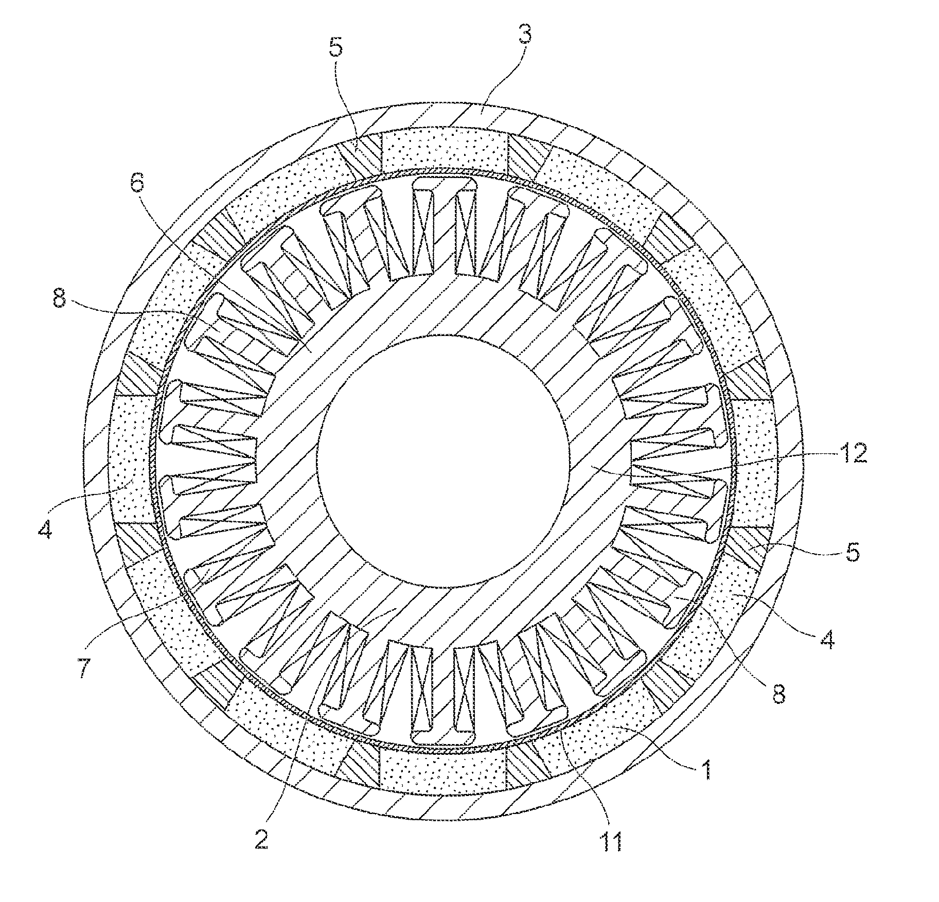
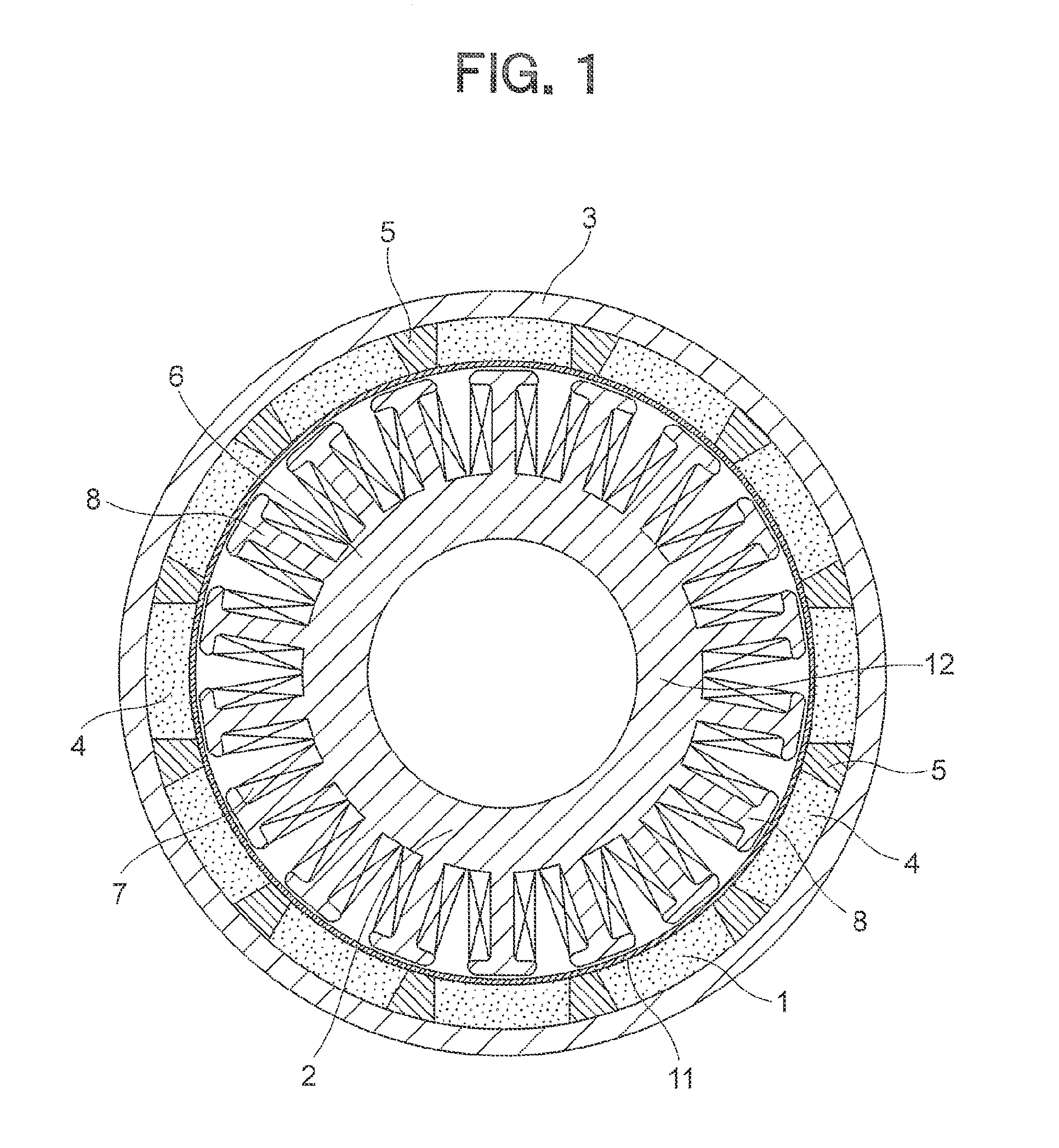
[0024]FIG. 1 is a front sectional view illustrating an AC generator for a vehicle (hereinafter abbreviated as “AC generator”) which is a magnet-type generator according to a first embodiment of the present invention, FIG. 2 is a partially enlarged view illustrating a rotor 1 illustrated in FIG. 1, FIG. 3 is a partial sectional view illustrating an AC generator which is a reference example, FIG. 4 is a partially enlarged view illustrating the AC generator illustrated in FIG. 1, and FIG. 5 is a partially enlarged view illustrating the rotor 1 illustrated in FIG. 1.

[0025]The AC generator, which is a magnet-type rotating electric machine, includes the rotor 1 and a stator 2. The rotor 1 is connected to an internal combustion engine through a shaft (not shown). The stator 2 is an armature provided inside of the rotor 1.

[0026]The rotor 1 includes a flywheel 3, a plurality of main magnets 4, a plurality of auxiliary magnets 5, and a pole tip 11. The flywheel 3 is a rotary body having a bow...

second embodiment

[0055]FIG. 6 is a front sectional view illustrating a principal part of a rotor 1 of an AC generator according to a second embodiment of the present invention.

[0056]In this embodiment, a concave portion 10 is formed between adjacent main magnets 4A on the outer circumferential side. In the concave portion 10, each of auxiliary magnets 5A is fitted.

[0057]The remaining configuration is the same as that of the AC generator of the first embodiment.

[0058]The auxiliary magnet 5A and the main magnet 4A repel against each other with a strong force. In this embodiment, however, the auxiliary magnet 5A is fitted into the concave portion 10. Therefore, the rotor 1 is prevented from losing rotation balance due to, for example, misalignment of the auxiliary magnet 5 during the rotation of the rotor 1.

[0059]Alternatively, a concave portion may be formed between the adjacent main magnets 4A on the inner circumferential side so that the auxiliary magnet is fitted into the concave portion.

third embodiment

[0060]FIG. 7 is a front sectional view of a principal part of a rotor 1 of an AC generator according a third embodiment of the present invention.

[0061]In this embodiment, a width b of an auxiliary magnet 5B in the circumferential direction is set with respect to a width a of a main magnet 4B in the circumferential direction so that a ratio b / a falls within the range of 1 / 10 to 1 / 2.

[0062]The remaining configuration is the same as that of the AC generator according to the first embodiment.

[0063]By providing the auxiliary magnet 5B, a volume of the main magnet 4B is inevitably reduced. Therefore, if the width b of each of the auxiliary magnets 5B in the circumferential direction is set extremely large, a volume of the main magnets 4B is reduced, which leads to a reduction in the amount of magnetic fluxes of the main magnets 4B, which are linked to the magneto coils 7.

[0064]In view of the above-mentioned problem, paying attention to the relationship between the ratio of the width of the...


PUM


Abstract

There is provided an alternating current generator for a vehicle, including: a rotor (1), a flywheel (3), and main magnets (4) and auxiliary magnets (5) alternately arranged; and a stator (2). Each of the main magnets (4) is magnetized to an N-pole and an S-pole in a radial direction, whereas the main magnets (4) are arranged so that the main magnets (4) adjacent to each other through corresponding one of the auxiliary magnets (5) therebetween are magnetized to have opposite polarity patterns. Each of the auxiliary magnets (5) is magnetized to the N-pole and the S-pole in the circumferential direction, whereas the auxiliary magnets (5) are arranged so that the auxiliary magnets (5) adjacent to each other through corresponding one of the main magnets (4) therebetween are magnetized to have opposite polarity patterns.

Description

BACKGROUND OF THE INVENTION[0001]1. Field of the Invention[0002]The present invention relates to a rotating electric machine including a rotor in which permanent magnets are arranged.[0003]2. Description of the Related Art[0004]The following AC generator for a vehicle is conventionally known as a magnet-type rotating electric machine. Specifically, permanent magnets are arranged on an inner wall surface of a bowl-like shaped flywheel so that the adjacent permanent magnets are magnetized to have opposite polarity patterns (for example, see Japanese Patent Application Laid-open No. 2008-193785; FIGS. 1 and 2).[0005]In the above-mentioned AC generator for a vehicle, the flywheel rotates interlockingly with a rotary shaft which is rotationally driven by an internal combustion engine. By alternating magnetic fields generated by the permanent magnets, power is generated from magneto coils provided inside of the flywheel.[0006]In the above-mentioned kind of magnet-type rotating electric ma...

Claims


Application Information

Patent Timeline
IPC IPC(8): H02K1/27H02K7/02
CPCH02K1/2786H02K7/02H02K21/222H02K1/2791
Inventor AKAMATSU, SHINGOBABA, SHINJI
Owner MITSUBISHI ELECTRIC CORP
Why Eureka
Try Eureka