Internal-Combustion-Engine Fuel Injection Control Device

a fuel injection control device and combustion engine technology, applied in the direction of electric control, fuel injection apparatus, charge feed system, etc., to achieve the effect of increasing the size or the cost of the fuel injection control devi

Active Publication Date: 2016-07-21
HITACHI ASTEMO LTD
View PDF5 Cites 11 Cited by
  • Summary
  • Abstract
  • Description
  • Claims
  • Application Information

AI Technical Summary

Benefits of technology

[0029]As it can be understood from the above description, according to the present invention, the boosting operation control unit configured to start the boosting operation at predetermined timing when the detected voltage in the booster circuit is higher than the threshold voltage for starting boosting and is lower than the threshold voltage for stopping boosting is included. Thus, for example, even in a case where a width of the fuel injection driving pulse to drive the fuel injection valve is small, a decrease in the boosted voltage is small, and the boosted voltage does not become lower than the threshold voltage for starting boosting, it is possible to start the boosting operation at predetermined timing, to accurately control a boosted voltage applied to the fuel injection valve during the fuel injection (at start of application of current), and to control a variation in the fuel injection amount without increasing a size or a cost of the fuel injection control device.
[0030]A problem, configuration, and effect other than what has been described above will be disclosed in a description of the following embodiments.

Problems solved by technology

The fuel injection control device accumulates the high voltage generated in the booster circuit into a charge accumulation element such as a capacitor and consumes the charge during the fuel injection.
As a result, a problem that a difference ΔIpeak in a point reached by the current flowing in the fuel injection valve 105′ (reached current value) is generated and that a fuel injection amount varies may be generated.

Method used


Image

  • Internal-Combustion-Engine Fuel Injection Control Device
  • Internal-Combustion-Engine Fuel Injection Control Device
  • Internal-Combustion-Engine Fuel Injection Control Device

Examples


first embodiment

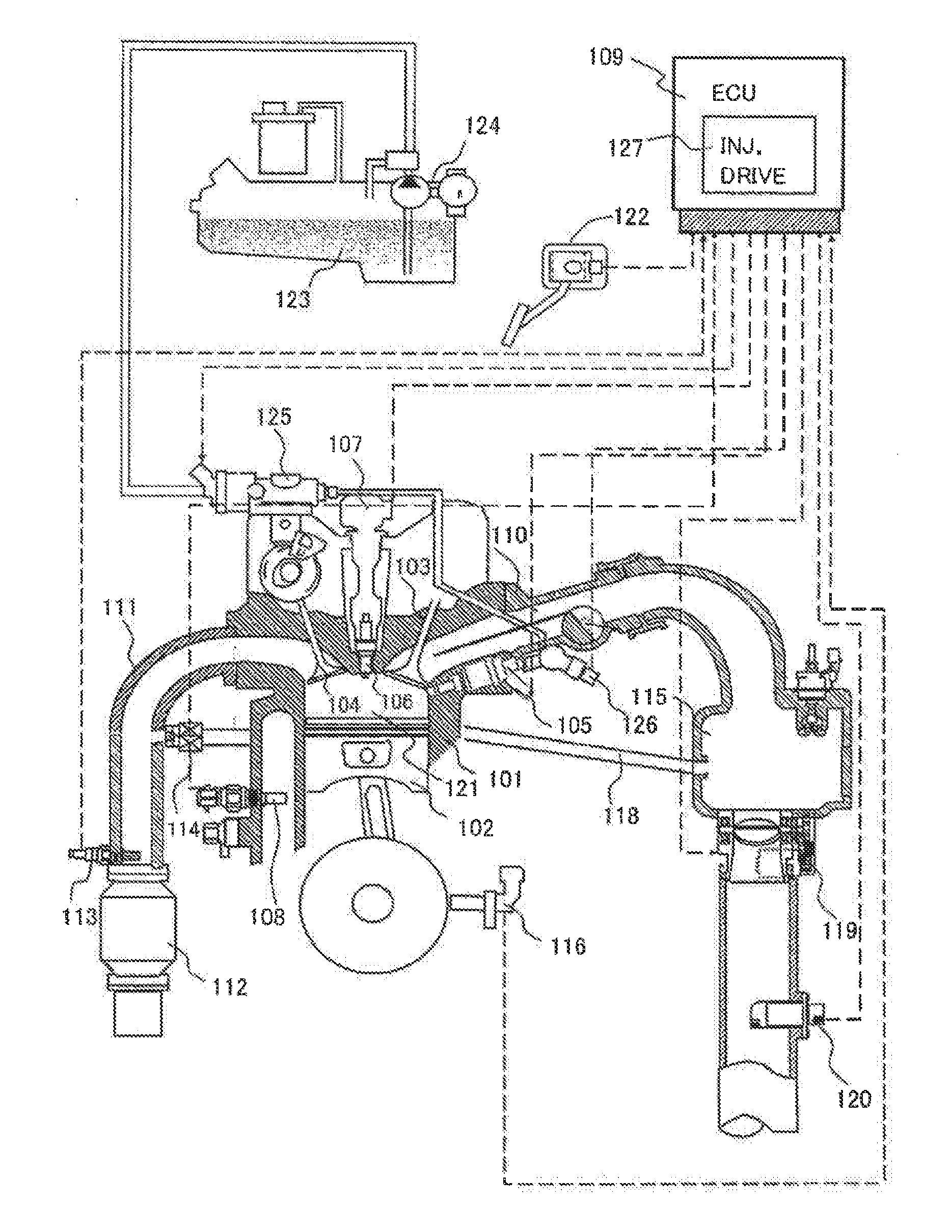
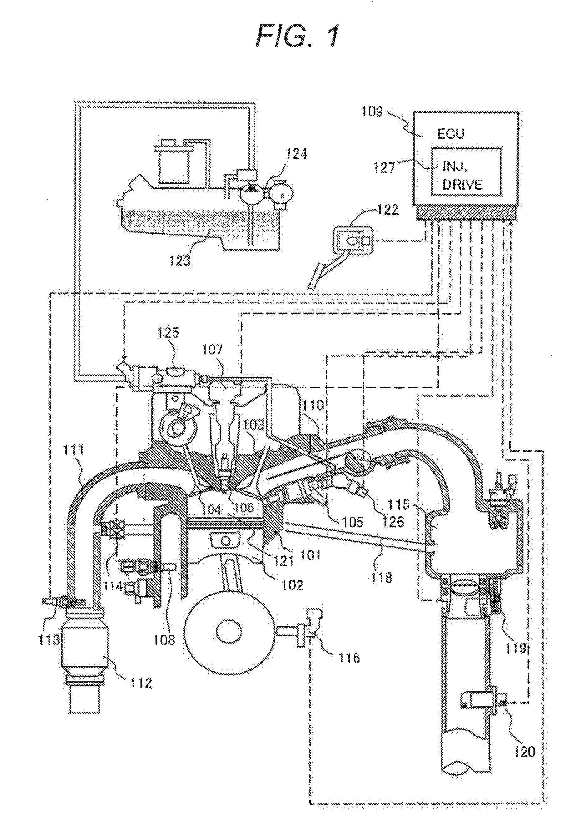
[0042]In FIG. 1, a whole configuration of an internal-combustion-engine including a first embodiment of an internal-combustion-engine fuel injection control device according to the present invention is schematically illustrated.

[0043]As illustrated in the drawings, an engine (internal-combustion-engine) 101 includes a piston 102, an intake valve 103, and an exhaust valve 104. After an amount of a flow of intake air necessary for combustion is measured by an air flow meter (AFM) 120, an amount of the air is adjusted by a throttle valve 119. Then, the air is supplied to a combustion chamber 121 of the engine 101 through a collector 115, an intake pipe 110, and the intake valve 103. Fuel is supplied from a fuel tank 123 to the engine 101 with a low-pressure fuel pump 124 and a pressure thereof is increased, by a high-pressure fuel pump 125, to a pressure with which fuel injection can be performed by a pressure in the combustion chamber 121 in a compression process. The high-pressure fu...

second embodiment

[0059]In FIG. 4, a circuit configuration of a second embodiment of an internal-combustion-engine fuel injection control device according to the present invention is illustrated. The fuel injection control device of the second embodiment illustrated in FIG. 4 includes a boosting operation control unit a configuration of which is different from that of the fuel injection control device of the first embodiment. The other configuration of the fuel injection control device of the second embodiment is similar to that of the fuel injection control device of the first embodiment. Thus, the same reference sign is assigned to a configuration similar to that of the first embodiment and a detail description thereof is omitted.

[0060]In a fuel injection control device 127 of the second embodiment, a boosted voltage is divided and input in a circuit of monitoring (or detecting) the boosted voltage in order to reduce a withstanding pressure of an input voltage in a comparator for recognizing a stop...

third embodiment

[0063]In FIG. 5, a circuit configuration of a third embodiment of an internal-combustion-engine fuel injection control device according to the present invention is illustrated. A fuel injection control device of the third embodiment illustrated in FIG. 5 includes a boosting operation control unit a configuration of which is different from that of the fuel injection control device of the second embodiment. The other configuration of the fuel injection control device of the third embodiment is similar to that of the fuel injection control device of the second embodiment. Thus, the same reference sign is assigned to a configuration similar to that of the second embodiment and a detail description thereof is omitted.

[0064]In a fuel injection control device 127 of the third embodiment, a capacitor C2 is used instead of the resistor R5 for changing a voltage division ratio in the second embodiment.

[0065]In the fuel injection control device 127, a switching element T14 is being off in norm...


PUM


Abstract

An internal-combustion-engine fuel injection control device which can accurately control a boosted voltage applied to a fuel injection valve during fuel injection and can control a variation in a fuel injection amount without increasing a size or a cost of the fuel injection control device even when a width of a fuel injection driving pulse to drive the fuel injection valve is small is provided. A fuel injection control device includes a boosting operation control unit configured to start a boosting operation at predetermined timing regardless of an amount of a detected voltage when the detected voltage is higher than a threshold voltage for starting boosting and is lower than a threshold voltage for stopping boosting.

Description

TECHNICAL FIELD[0001]The present invention relates to an internal-combustion-engine fuel injection control device. For example, the present invention relates to an internal-combustion-engine fuel injection control device to inject fuel into a combustion chamber by opening a fuel injection valve with a booster circuit.BACKGROUND ART[0002]Conventionally, a technology of directly injecting fuel into a cylinder has been practically used as a technology of fuel injection to an internal-combustion-engine.[0003]Also, recently, since it is requested to make exhaust gas cleaner and to improve fuel efficiency, power, and the like, fuel injection into a cylinder is divided into a plurality of times (multi stage injection) and downsizing to combine a supercharger with an internal-combustion-engine and to reduce displacement, is in progress. Thus, in order to deal with the minimum output to the maximum output of the internal-combustion-engine, a further expansion of a dynamic range from the mini...

Claims


Application Information

Patent Timeline
Patent Type & Authority Applications(United States)
IPC IPC(8): F02D41/20
CPCF02D2041/2013F02D41/20F02D2041/2048F02D2041/2051F02D2041/2058
Inventor FUKUDA, TAKAOSAKAMOTO, HIDEYUKITOYOHARA, MASAHIROFUJII, YOSHIHISAMUKAIHARA, OSAMUWATANABE, MITSUHIKOKONNO, TAKESHI
Owner HITACHI ASTEMO LTD
Why Eureka
Try Eureka