
Golf course flag retention device

Inactive Publication Date: 2005-09-06
ASH KEVIN C
View PDF18 Cites 24 Cited by
  • Summary
  • Abstract
  • Description
  • Claims
  • Application Information

AI Technical Summary

Benefits of technology

[0012]The present invention provides for a system, method and device for attachment to a golf flagstick. Through interaction with a golf hole cup, the invention prevents indentation damage to the earthen rim of the golf hole, and abrasion damage to the flagstick itself. It also provides a means for retaining the flag in the cup and preventing high winds or other lateral pressures from unwanted removal from the cup.

Problems solved by technology

However, the typical prior art flagstick 12, ferrule 16 and cup 20 assembly does not adequately handle strong lateral forces directed against the golf flag 36 and flagstick 12 assembly.
Repeated contact in this fashion with the rigid cup rim 50 results in accumulating abrasive damage to the flagstick 12.
It is readily apparent that such damage will necessitate the replacement of the flagstick 12.
Another problem caused by strong winds is that the golf flag 10 may be blown out of the cup 20 entirely.
This results in damage to the putting surface S when the metal ferrule 16 falls and strikes the putting surface S with the weight of the flag 10 assembly.

Method used


Image

  • Golf course flag retention device
  • Golf course flag retention device
  • Golf course flag retention device

Examples


embodiment 180

[0045]FIG. 11 shows a cup-shaped conical embodiment 180 of the present invention. The bottom surface 182 is shaped to follow the contours of the inner surface of the bottom of a USGA cup 20, or any other desired golf cup. The conical embodiment 180 is attached to a flagstick 12 at a point aligning the bottom surface 182 with the top of the ferrule 16, thereby enabling the bottom surface 182 to engage the cup inner surface when inserted within the cup.

embodiment 190

[0046]FIG. 12 shows another cup-shaped conical embodiment 190 of the present invention. The bottom surface 191 is shaped to follow the contours of the inner surface of the bottom of a USGA cup 20, or any other desired golf cup. Fins 192 are projected from the bottom surface 191 for insertion into cup webbing voids. In the example shown in FIG. 16, the fins 192 are formed for cooperative insertion into standard USGA cup web voids 25. The fins 192 engage the cup web elements 27 and thereby help secure a flag assembly (not shown) incorporating the embodiment 190 in a vertical alignment in resistance to horizontal wind components.

embodiment 200

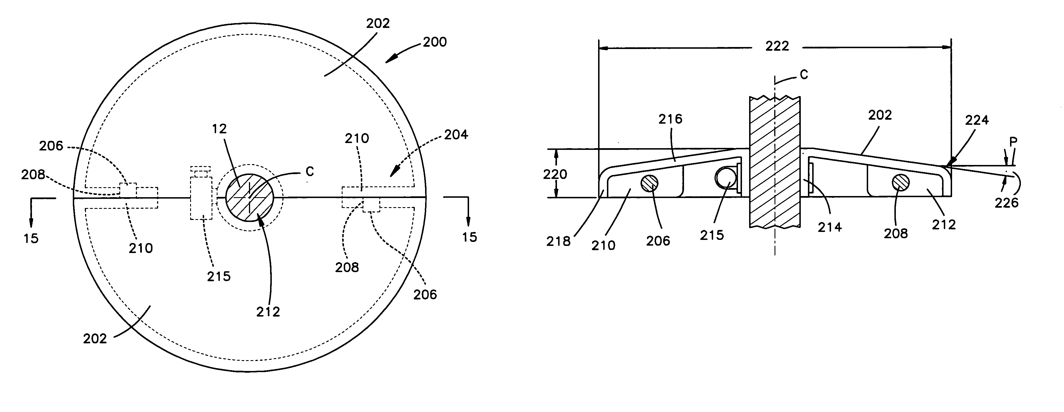
[0047]FIG. 14 is a top plan view of another embodiment 200 of the present invention. FIG. 15 is a sectional view of the embodiment 200 of FIG. 14. Two semi-circular discs 202 defined about a centerline C are provided for connecting to each other by a plug-and-hole means 204 to form the assembly 200. A projecting plug 206 is formed on a male mounting flange 210, and an aperture 208 for receiving a plug 206 is defined by a female mounting flange 212. The disc 202 defines a semi-circular aperture 212 about the centerline C for receiving a typical golf flagstick shaft 12. By aligning the shaft apertures 212 about a flagstick shaft 12 and pressing each plug 206 into a corresponding aperture 208, two semi-circular discs 202 can be connected together to form an assembly 200 about a typical golf flag shaft 12.

[0048]The discs 202 may be attached to the flagstick shaft 12 by clamping the shaft aperture side-walls 214 against the shaft 12 with a typical band clamp 215. The band clamp 215 also ...


PUM


Abstract

The present invention provides for a system, method and device for attachment to a golf flagstick. Through interaction with a golf hole cup, the invention prevents indentation damage to the earthen rim of the golf hole, and abrasion damage to the flagstick itself. It also provides a means for retaining the flag in the cup, preventing high winds or other lateral pressures from unwanted removal from the cup.

Description

REFERENCE TO RELATED APPLICATION[0001]This application is a continuation-in-part of and claims the effective priority filing date of a previous provisional application filed in the United States Patent and Trademark Office by Kevin C. Ash on Jan. 17, 2003, titled “GOLF COURSE FLAG RETENTION DEVICE” and assigned Ser. No. 60 / 441,011.BACKGROUND OF THE INVENTION[0002]The present invention relates to golf course flagsticks. As is well known, a golf course flagstick is designed to be inserted into a golf course hole and stand in an upright fashion. A flag is typically attached to the top of the flagstick, and the flagstick and flag provide a visual indicator for golfers to inform them as to the exact location of the hole, and thereby provide a target for their approach shots toward the hole.[0003]FIGS. 1 and 2 illustrate a typical United States Golf Association (USGA) approved standard golf course flag 10 inserted into a conventional USGA golf cup 20. Although USGA regulation flagsticks a...

Claims


Application Information

Patent Timeline
IPC IPC(8): A63B57/00A63B71/02
CPCA63B57/0056A63B71/028A63B57/357A63B57/40
Inventor ASH, KEVIN C.
Owner ASH KEVIN C
Features
  • Generate Ideas
  • Intellectual Property
  • Life Sciences
  • Materials
  • Tech Scout
  • Unparalleled Data Quality
  • Higher Quality Content
  • 60% Fewer Hallucinations
Learn More