Thermally efficient micromachined device

a micromachined device and thermal insulation technology, applied in the direction of hydrogen/synthetic gas production, metal/metal-oxide/metal-hydroxide catalysts, chemical production, etc., can solve the problems of reducing the overall efficiency of the system, unable to maintain the thermal gradient and thermal insulation required for efficient fuel processing, and preventing the use of the device for portable power generation

Inactive Publication Date: 2005-09-06
MASSACHUSETTS INST OF TECH
View PDF39 Cites 60 Cited by
  • Summary
  • Abstract
  • Description
  • Claims
  • Application Information

AI Technical Summary

Benefits of technology

[0018]Embodiments of the micromachined device of the present invention address the difficulties described above encountered in adapting such devices for use in portable power generation. Micromachined devices constructed according to the present invention may be adapted for conducting chemical reactions with fluidic reactants wherein the device consumes substantially less energy than can be produced from the fluid products. These and other advantages of the present invention will be apparent on consideration of the following detailed description of embodiments of the invention. The reader also may comprehend additional details and advantages of the present invention upon making and / or using the micromachined device of the present invention.

Problems solved by technology

The power consumed in sustaining those temperatures reduces the overall efficiency of the system.
As device dimensions become smaller, it becomes increasingly difficult to maintain the thermal gradients and thermal insulation required for efficient fuel processing.
Often with existing micromachined fuel processing devices, significantly more power is required to maintain the temperature within the high temperature regions of the device than is contained in the fuel, precluding the device's use for portable power generation.
However, the present inventors have concluded that micromachined fluidic devices add three unique difficulties: the need for enclosed fluidic structures connecting the thermal regions; the potential of added heat flow through thermal convection; and, frequently, a desire to include regions where the walls of the fluid conducting tube are held isothermal.

Method used


Image

  • Thermally efficient micromachined device
  • Thermally efficient micromachined device
  • Thermally efficient micromachined device

Examples


example 1

[0092]FIG. 8(a) and FIG. 8(b) show the results of a finite element simulation of fluid and heat flow in one fluid conducting tube 205 in a micromachined device constructed according to the present invention and adapted for combusting a fuel. This particular simulation models the heat exchange for a device burning 1 watt of a stoichiometric butane-air mixture at 1652° F. (900° C.) with the substrate held at 86° F. (30° C.), neglecting losses from the exterior surface of the tube and thermally conductive structures. Note, however, that any combustible fuel may be used. The cold stream of fluid enters the inlet portion 205b of the fluid conducting tube 205 from the substrate 203, is preheated by the fluid exiting the thermally conductive region 202, combusts in the intermediate portion of the fluid conducting tube (which is encased in the thermally conductive region 202), and returns to the substrate 203 via the outlet portion 205a of the fluid conducting tube 205. These simulations in...

example 2

[0093]Theoretical analysis of the behavior of the thermally conductive region as an ammonia cracker has been carried out. Results of this analysis are provided in FIG. 9. The system was assumed to use the combustion of hydrogen from a fuel cell anode to supply the energy to achieve elevated temperatures in the thermally conductive region for the endothermic ammonia cracking reaction. It was assumed that enough catalyst would be present to crack 30 sccm of ammonia at 1652° F. (900° C.). The temperature of the thermally conductive region was varied to reflect the need for higher cracking temperatures at higher ammonia flow rates. An optimal operating point for the device based on the increased importance of conductive thermal losses for lower power operation and poor recuperation of exhaust heat at higher power levels and ammonia flow rates is expected.

example 3

[0094]As depicted in FIG. 10(a), one particular approach to using the described gas-phase reactor of the present invention in a portable power application is the thermal decomposition of a fluid reactant into fluid products. In this example the fluid reactant is ammonia gas and the fluid products are hydrogen and nitrogen for use in a fuel cell. Hydrogen is the preferred fuel of many fuel cell systems. It is, however, difficult and dangerous to store and transport. This approach allows ammonia to be transported, which results in increased energy storage density.

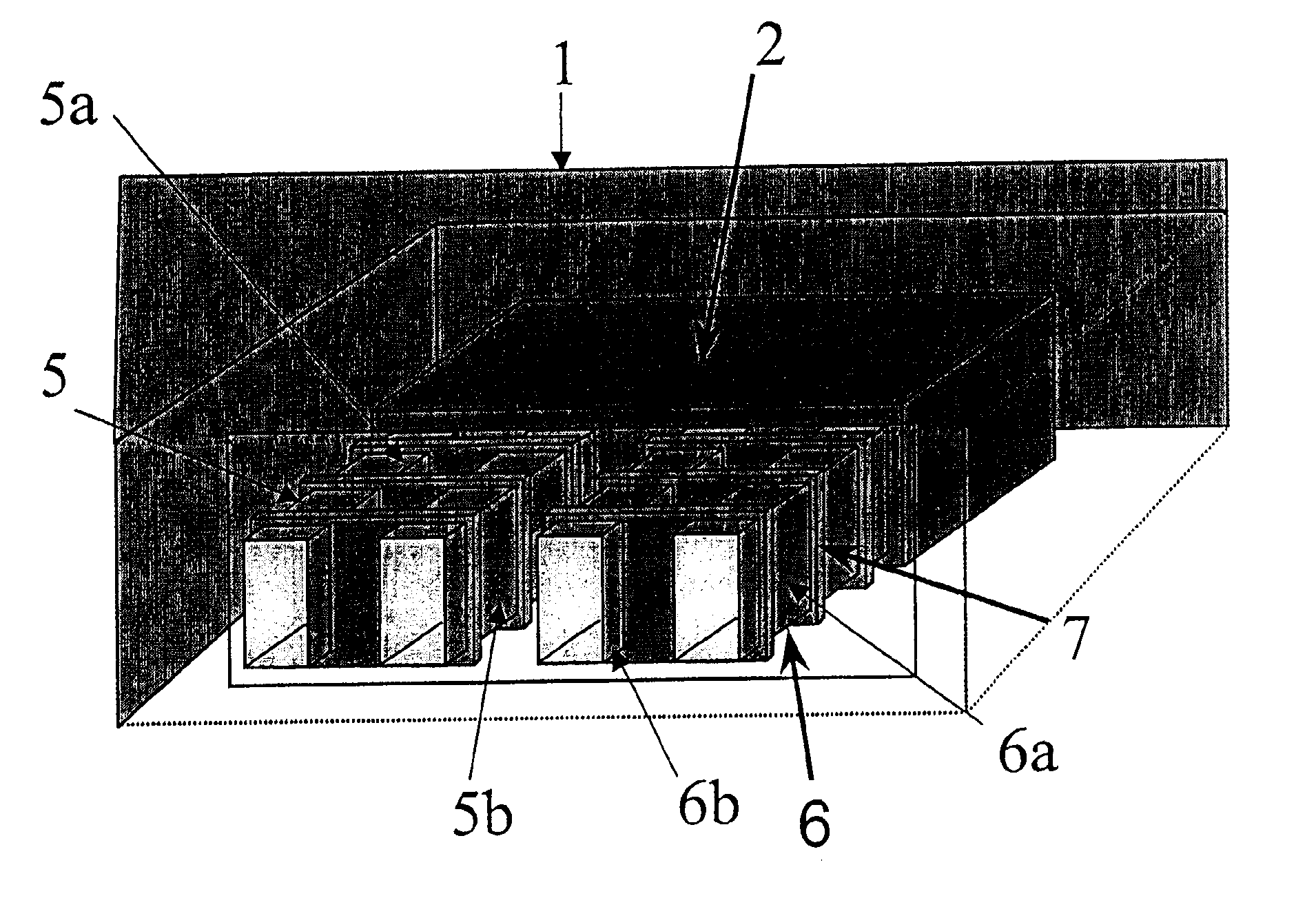
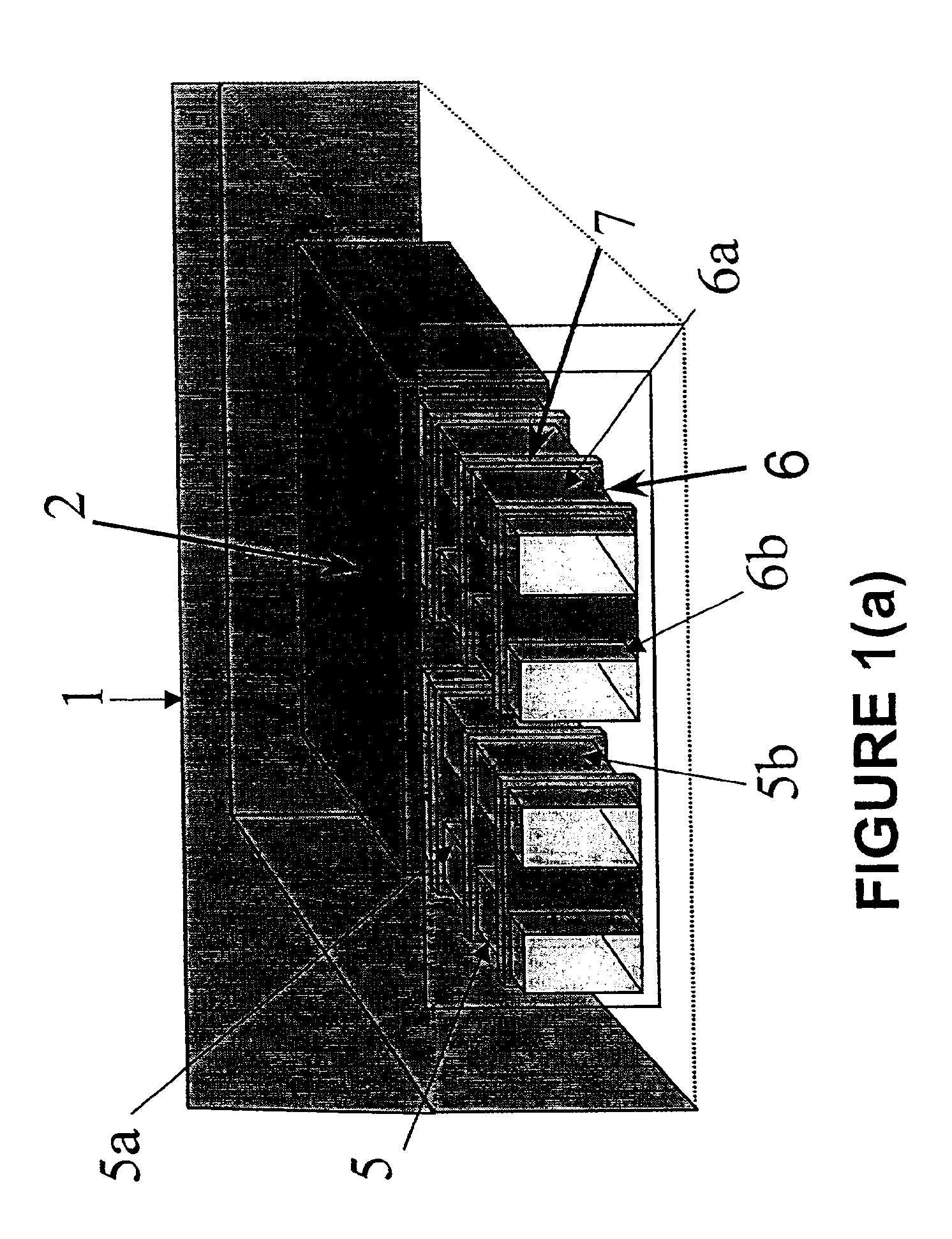
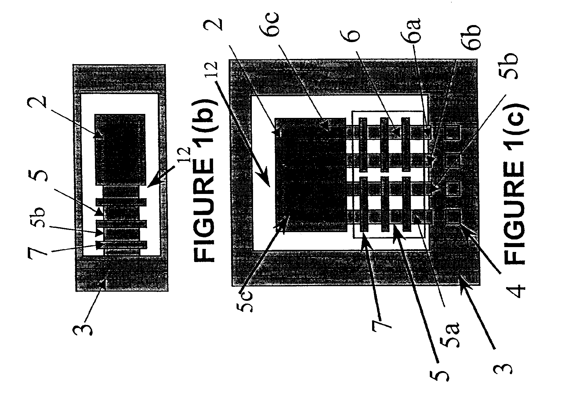
[0095]The ammonia decomposition approach would use the thermally insulating inlet portion 5b of a fluid conducting tube 5 to carry ammonia gas into intermediate portion 5c of the fluid conducting tube 5. The intermediate portion 5c is encased in the thermally conductive region 2, which is comprised of silicon or another material of high thermal conductivity. The thermally conductive region 2 is maintained at an elevated tempe...


PUM

PropertyMeasurementUnit
thicknessaaaaaaaaaa
wall thicknessaaaaaaaaaa

Abstract

A micromachined device for efficient thermal processing at least one fluid stream includes at least one fluid conducting tube having at least a region with wall thickness of less than 50 μm. The device optionally includes one or more thermally conductive structures in thermal communication with first and second thermally insulating portions of the fluid conducting tube. The device also may include a thermally conductive region, and at least a portion of the fluid conducting tube is disposed within the region. A plurality of structures may be provided projecting from a wall of the fluid conducting tube into an inner volume of the tube. The structures enhance thermal conduction between a fluid within the tube and a wall of the tube. A method for fabricating, from a substrate, a micromachined device for processing a fluid stream allows the selective removal of portions of the substrate to provide desired structures integrated within the device. As an example, the micromachined device may be adapted to efficiently react fluid reactants to produce fuel for a fuel cell associated with the device, resulting in a system capable of conversion of chemical to electrical energy.

Description

STATEMENT REGARDING FEDERALLY SPONSORED RESEARCH OR DEVELOPMENT[0001]Work related to the present invention was supported in part under DARPA Contract No. F30602-99-2-0544. The government may have certain rights in the invention.CROSS REFERENCE TO RELATED APPLICATIONS[0002]Not applicable.TECHNICAL FIELD AND INDUSTRIAL APPLICABILITY OF THE INVENTION[0003]The present invention is generally directed to a micromachined device for efficient thermal processing of fluids. More particularly, the present invention is directed to a micromachined device for carrying out fluid processing with improved thermal efficiency. As used herein, fluid processing includes, for example, subjecting a stream of a fluid to chemical reactions, heating, cooling, filtration, adsorption, desorption, and / or phase changes (e.g., evaporation and condensation). The present invention may be used in, for example, the processing of chemicals for purposes of power generation.DESCRIPTION OF THE INVENTION BACKGROUND[0004]T...

Claims


Application Information

Patent Timeline
Patent Type & Authority Patents(United States)
IPC IPC(8): B01L3/00B01F13/00B01J19/00B01F5/06C01B3/32C01B3/04C01B3/00C01B3/38H01M8/04H01M8/06B01J23/46B01J35/00B01J35/04B81B1/00
CPCB01F5/0618B01F13/0059B01J19/0093B01L3/5027C01B3/047C01B3/323C01B3/386H01M8/04097H01M8/04201H01M8/0606B01F2005/0621B01F2005/0636B01J23/468B01J35/04B01J2219/00783B01J2219/00828B01J2219/00835B01J2219/0086B01J2219/00873B01J2219/00889B01L2200/14B01L2300/1805B01L2300/1883C01B2203/0233C01B2203/0261C01B2203/066C01B2203/0811C01B2203/0822C01B2203/1223C01B2203/1247C01B2203/1282F28F3/12F28F2260/02H01M2250/405Y02E60/364Y02E60/50Y02B90/16Y02P20/52Y02B90/10Y02E60/36Y02P20/10B01F25/4316B01F25/4317B01F25/431971B01F33/30B81B7/00
Inventor ARANA, LEONEL R.FRANZ, ALEKSANDER J.JENSEN, KLAVS F.SCHAEVITZ, SAMUEL B.SCHMIDT, MARTIN A.
Owner MASSACHUSETTS INST OF TECH
Why Eureka
Try Eureka