Variable capacitance type input device

Inactive Publication Date: 2005-09-06
NITTA CORP +1
View PDF6 Cites 34 Cited by
  • Summary
  • Abstract
  • Description
  • Claims
  • Application Information

AI Technical Summary

Benefits of technology

[0005]It is hence an object of the present invention to provide a

Problems solved by technology

In the above capacitance type sensor, in order to ensure a gap between the movable electrode plate D and the fixed electrodes Dx+, Dx−, Dy+, Dy− and

Method used


Image

  • Variable capacitance type input device
  • Variable capacitance type input device
  • Variable capacitance type input device

Examples


Embodiment Construction

[0018]The present invention will be described below with reference to the accompanying drawings showing preferred embodiments.

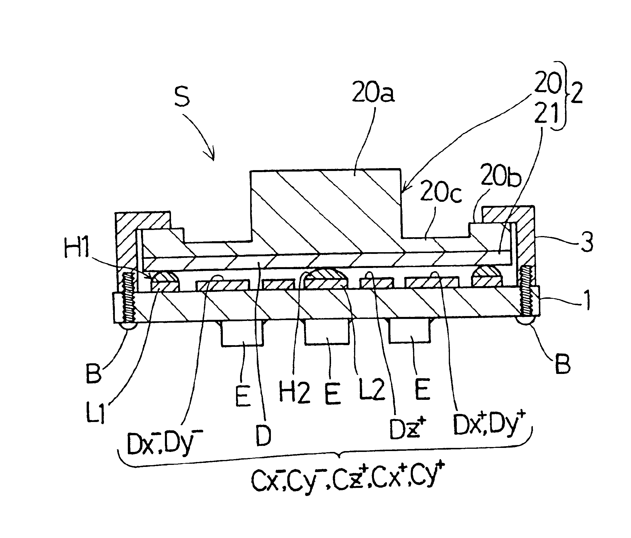
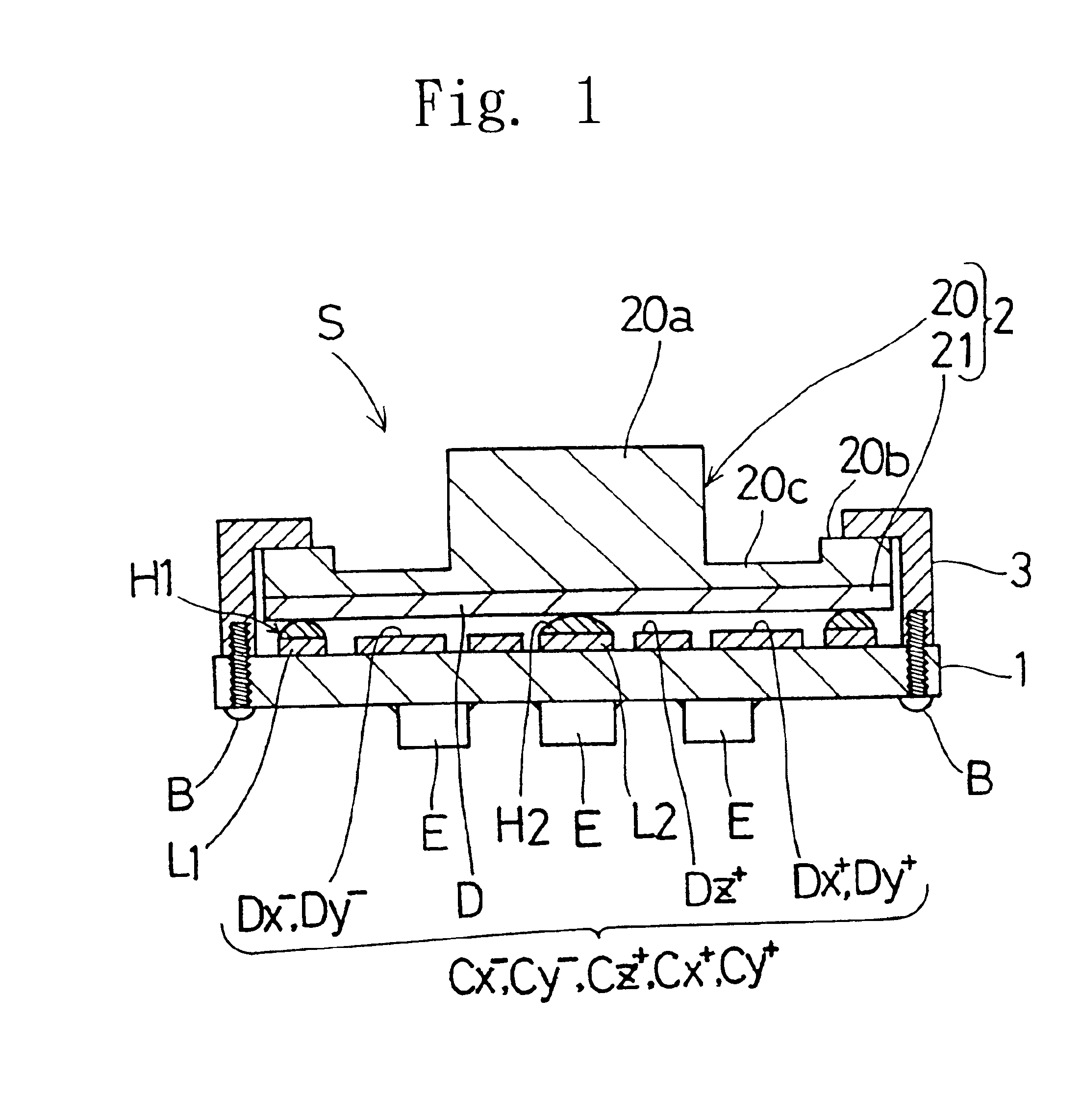
[0019]FIG. 1 illustrates a cross-sectional view of a capacitance type sensor S according to an embodiment of the present invention.

[0020]Referring to FIG. 1, the capacitance type sensor S basically includes a substrate 1 and a movable electrode plate 2 provided with a gap with respect to the substrate 1. The substrate 1 and the movable electrode plate 2 are disposed so as not to be separated from each other by a fixing member 3 attached to the substrate 1 with screws B.

[0021]The main construction of the capacitance type sensor S will be described below in detail.

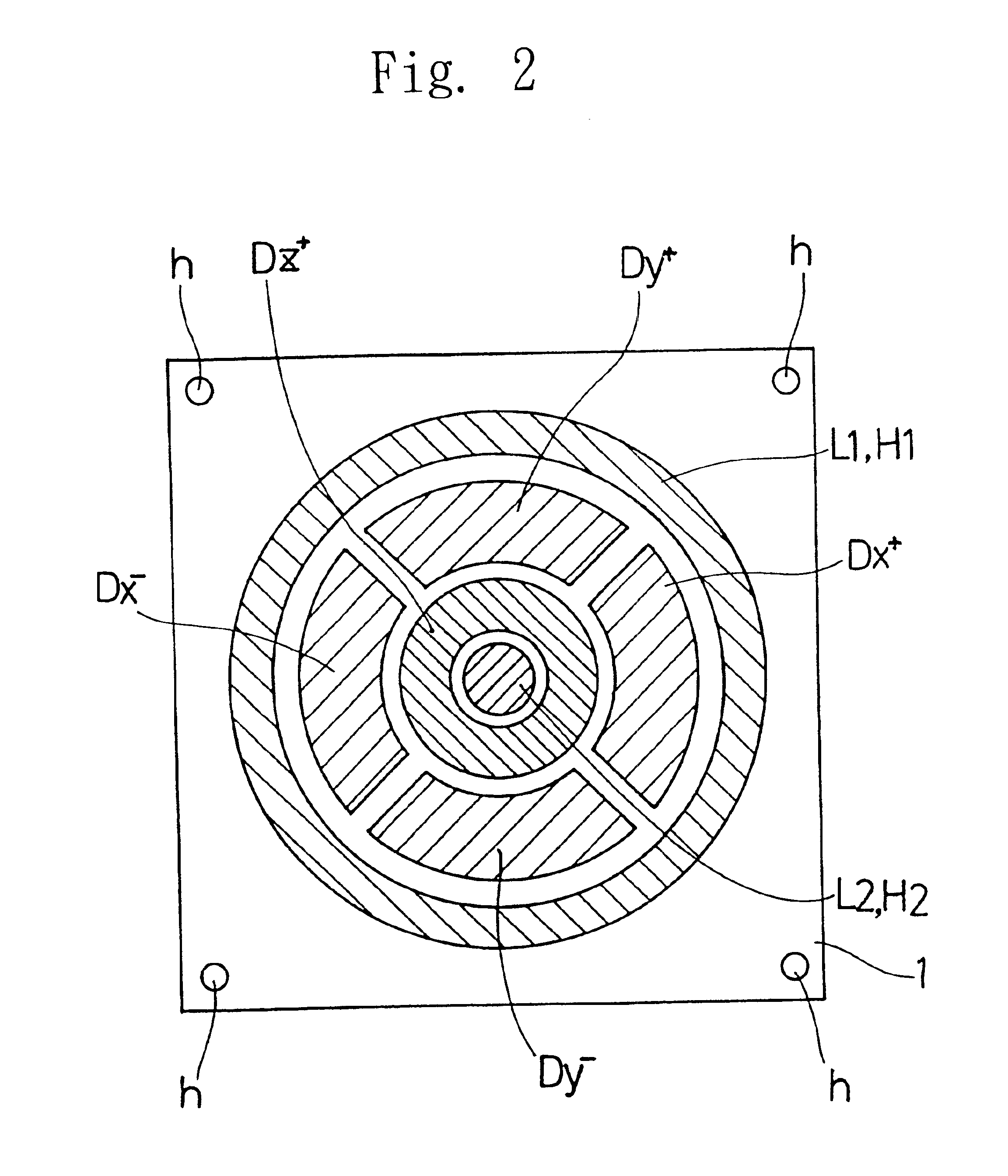
[0022]Referring to FIGS. 1 and 2, the substrate 1 has, on its upper face, lands L1 and L2 for contact points (contact lands) and fixed electrodes Dx+, Dx−, Dy+, Dy− and Dz+ covered with resist films (no shown). On the lower face, the substrate 1 has electronic components E for capacitance / voltage conv...


PUM


Abstract

A capacitance type sensor includes a substrate, a group of electrodes fixed on an upper face of the substrate, a movable electrode plate having an electrode on its lower side and a gap between the group of fixed electrodes on the substrate and the electrode on the movable electrode plate. The gap is formed with a solder layer, a conductive elastomer layer, a conductive paint layer, or a conductive adhesive material layer provided on the substrate. The electrode on the movable electrode plate is made of conductive rubber plate or conductive elastomer plate.

Description

BACKGROUND OF THE INVENTION[0001]The present invention relates to a capacitance type sensor, which specifically can be used as a joy stick or a pointing device.[0002]The capacitance type sensor shown in FIG. 7 is developed by the inventors of the present application and a patent has been filed in Japan.[0003]In FIG. 7, the capacitance type sensor includes a substrate 90, a movable electrode plate D, an operation part 92 and a fixing member 93. The substrate 90 has fixed electrodes Dx+, Dx−, Dy+, Dy− and Dz+ thereon. The movable electrode plate D has faces, and at least one of the faces which is opposing the fixed electrodes Dx+, Dx−, Dy+, Dy− and Dz+ is made of conductive rubber. The operation part 92 is made of silicone rubber and integrally formed with the movable electrode plate D. The fixing member 93 presses down the movable electrode plate D and the operation part 92 and prevents them from separating from the substrate 90. The fixed electrodes Dx+, Dx−, Dy+, Dy− and Dz+ and th...

Claims


Application Information

Patent Timeline
IPC IPC(8): G06F3/033G01L1/14G01L5/16
CPCG06F3/0338
Inventor MORIMOTO, HIDEOOKADA, KAZUHIRO
Owner NITTA CORP
Why Eureka
Try Eureka