
Resistive down hole heating tool

a technology of resistive down hole and heating tool, which is applied in the direction of insulation, fluid removal, tunnel/mine ventillation, etc., can solve the problems of increased cost, increased size and complexity of drilling equipment, and high cost of wo

Inactive Publication Date: 2005-09-13
CANITRON SYST
View PDF7 Cites 110 Cited by
  • Summary
  • Abstract
  • Description
  • Claims
  • Application Information

AI Technical Summary

Benefits of technology

[0009]In our recently issued U.S. Pat. No. 6,384,389 (Spencer), the contents of which are incorporated herein by reference and in our co-pending application Ser. No. 10/289,9127, filed Nov. 6, 2002 and entitled DOWNHOLE INDUCTION HEATING TOOL AND METHOD OF USING SAME, the co

Problems solved by technology

The WOC is expensive and disadvantageous.
The deeper the well, the higher the costs which costs increase with the greater size and complexity of the drilling equipment necessary for the deep drilling.

Method used


Image

  • Resistive down hole heating tool
  • Resistive down hole heating tool
  • Resistive down hole heating tool

Examples


Embodiment Construction

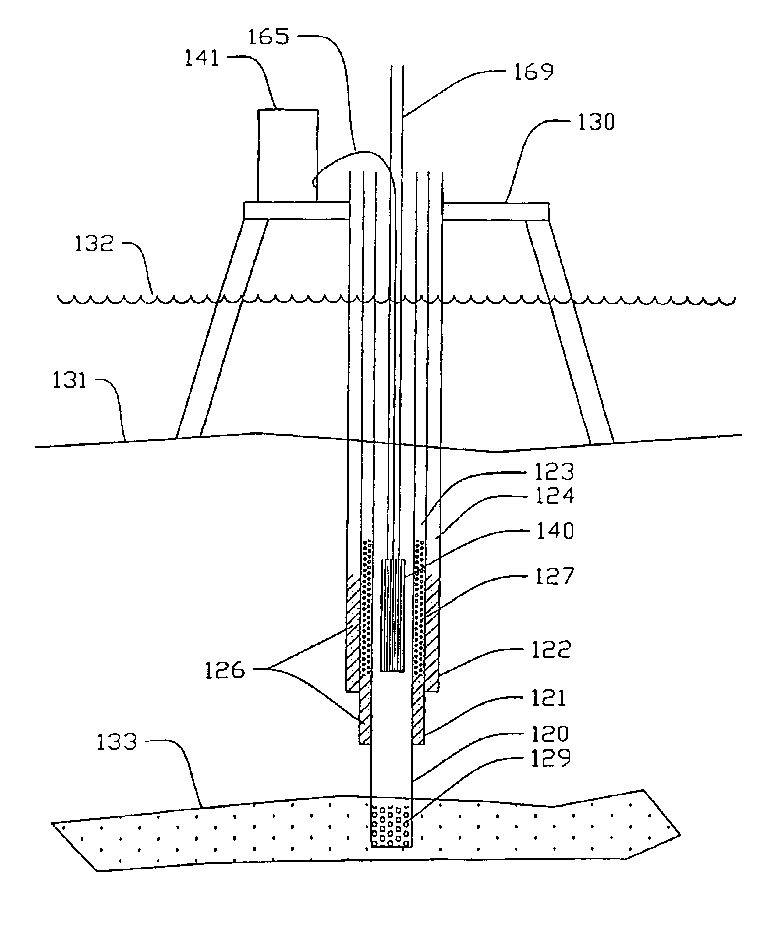
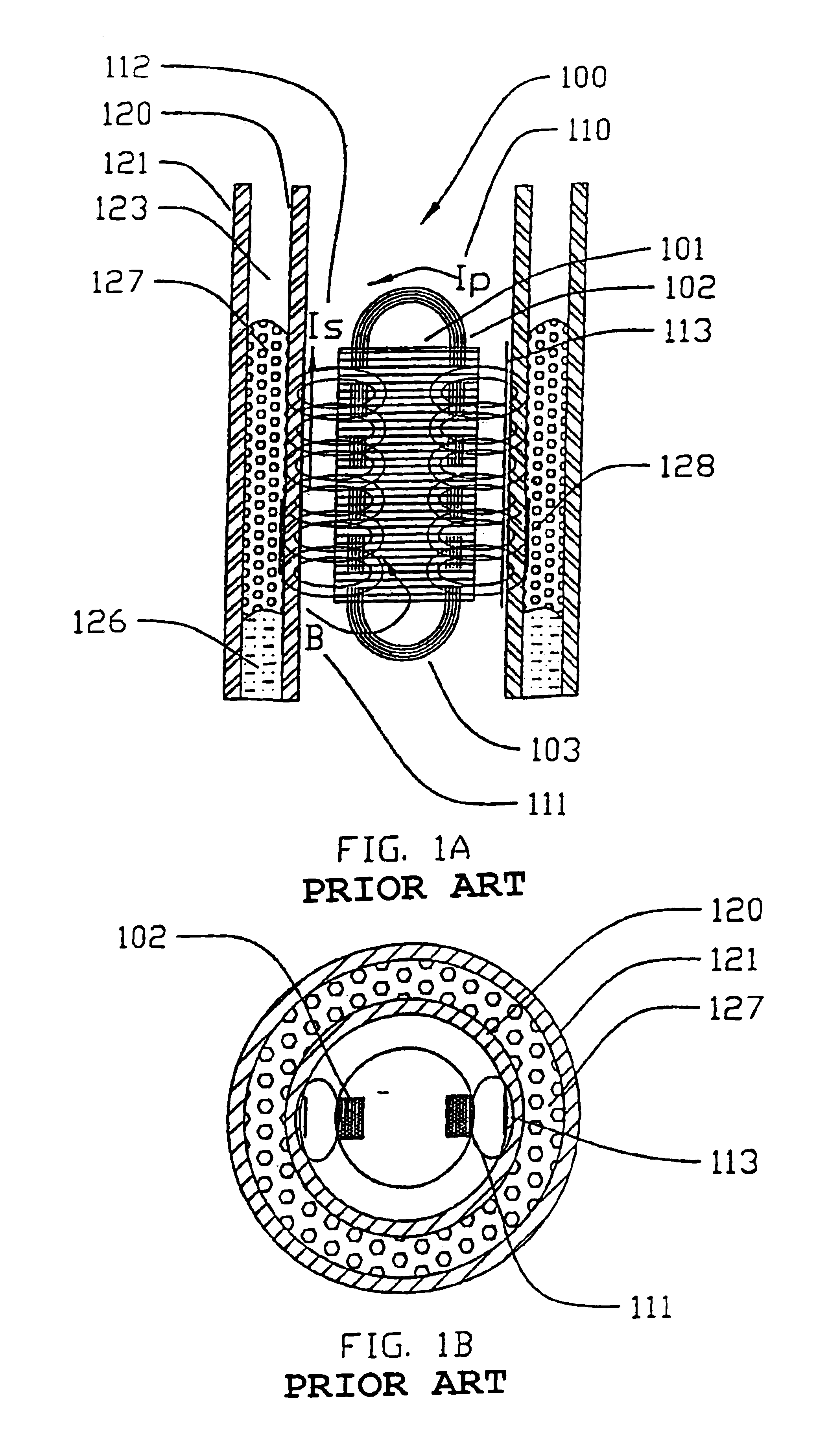
[0037]Referring now to the drawings, there is provided a well inductive heating tool generally illustrated at 100 according to the PRIOR ART which tool is illustrated in FIG. 1. Such a tool is illustrated and described in our U.S. Pat. No. 6,384,389, the contents of which are disclosed herein by reference.

[0038]The well inductive heating tool 100 is used for downhole well heating as will be described further in association with FIG. 2. However, the tool 100 illustrated in FIGS. 1A and 1B comprises a laminated magnetically permeable core 101 with the core laminations running orthogonal to the axis of the tool 100 and casing 03120 and with coil windings 102, 103 which are wrapped about the core 101 in a direction normal to the direction of the laminations made from the magnetically permeable material of core 101.

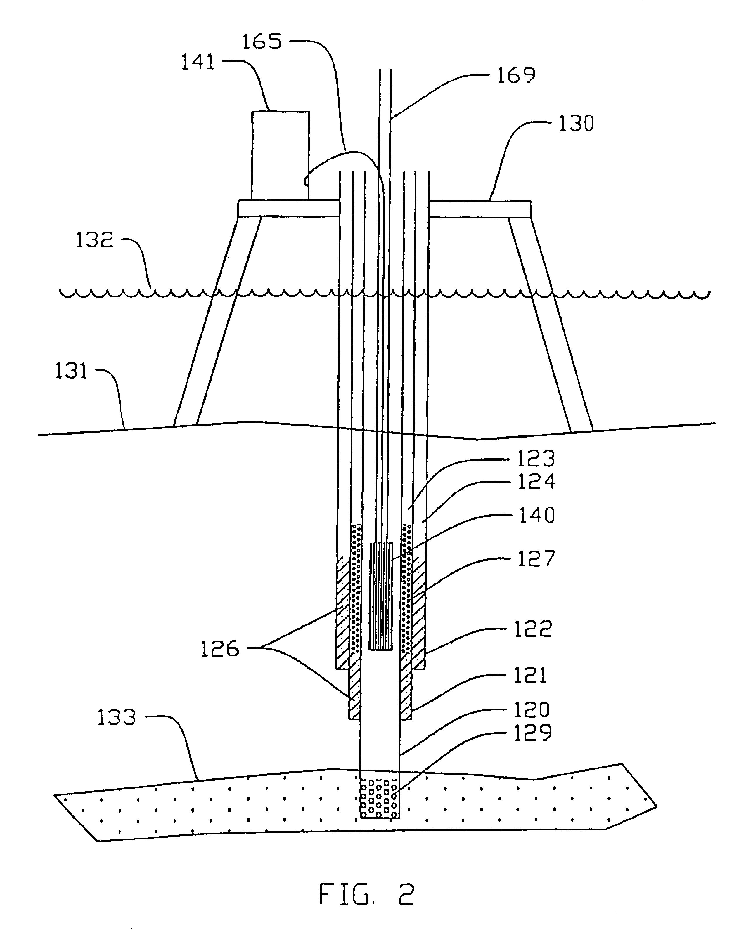
[0039]The tool 100 is lowered and positioned to desired depth into the circumferential well casing 120. Electric current is applied to the coil windings 102. The instantaneous...


PUM


Abstract

A heating tool used for heating cement and / or a ground formation zone and melting billets in a down hole application for sealing oil and gas wells from gas migration. The heating tool has a billet loader which allows a plurality of billets to be loaded into the top of the tool and which billets then pass downward into a magazine and the lowermost heating area of the tool to rest on a billet retainer.

Description

CROSS-REFERENCE TO RELATED APPLICATION[0001]This application is a continuation-in-part of application Ser. No. 10 / 308,867 filed Dec. 2, 2002 and entitled METHOD AND APPARATUS FOR CEMENT INJECTION AND THERMAL ACTIVATION which is a continuation-in-part of application Ser. No. 10 / 289,917 filed Nov. 6, 2002 and entitled DOWNHOLE INDUCTION HEATING TOOL AND METHOD OF USING SAME.INTRODUCTION[0002]This invention relates to a resistive type down hole heating tool and, more particularly, to a resistive type down hole heating tool which melts a bismuth alloy based material and the cement and ground formation into which the melted bismuth alloy material flows.BACKGROUND OF THE INVENTION[0003]Completion procedures for oil and gas wells include lining the drilled hole with a steel casing. The casing is held in place by pumping cement formulations down the casing and upwards into the annular space between the outside surface of the casing and the wall of the wellbore. Typically, successive casing ...

Claims


Application Information

Patent Timeline
IPC IPC(8): E21B36/04E21B33/13E21B33/14E21B36/00H05B6/02H05B6/10
CPCE21B33/14E21B36/04H05B6/101H05B6/105
Inventor LA ROVERE, THOMAS A.SPENCER, HOMER L.
Owner CANITRON SYST
Features
  • Generate Ideas
  • Intellectual Property
  • Life Sciences
  • Materials
  • Tech Scout
  • Unparalleled Data Quality
  • Higher Quality Content
  • 60% Fewer Hallucinations
Learn More