Terminal holding and heat dissipating structure

a technology of holding structure and heat dissipation structure, which is applied in the direction of printed circuit manufacturing, transportation and packaging, light and heating apparatus, etc., can solve the problems of solder cracks and solder cracks liable to occur in the soldered portion, and achieve the effect of dissipating the structure of the terminal, preventing the occurrence of solder cracks, and alleviating the dynamic stress on the soldered portion

Inactive Publication Date: 2005-09-13
YAZAKI CORP
View PDF16 Cites 16 Cited by
  • Summary
  • Abstract
  • Description
  • Claims
  • Application Information

AI Technical Summary

Benefits of technology

[0012]Accordingly, the invention has been devised to overcome the above-described problems, and its object is to provide a terminal structure which makes it possible to alleviate stresses including the mechanical stress and the thermal stress applied to the soldered portion, thereby making it possible to reliably prevent the occurrence of the solder crack.

Problems solved by technology

Hence, a solder crack has been liable to occur in the soldered portion 8.

Method used


Image

  • Terminal holding and heat dissipating structure
  • Terminal holding and heat dissipating structure
  • Terminal holding and heat dissipating structure

Examples


Embodiment Construction

[0051]Referring now to the drawings, a description will be given of an embodiment of the invention.

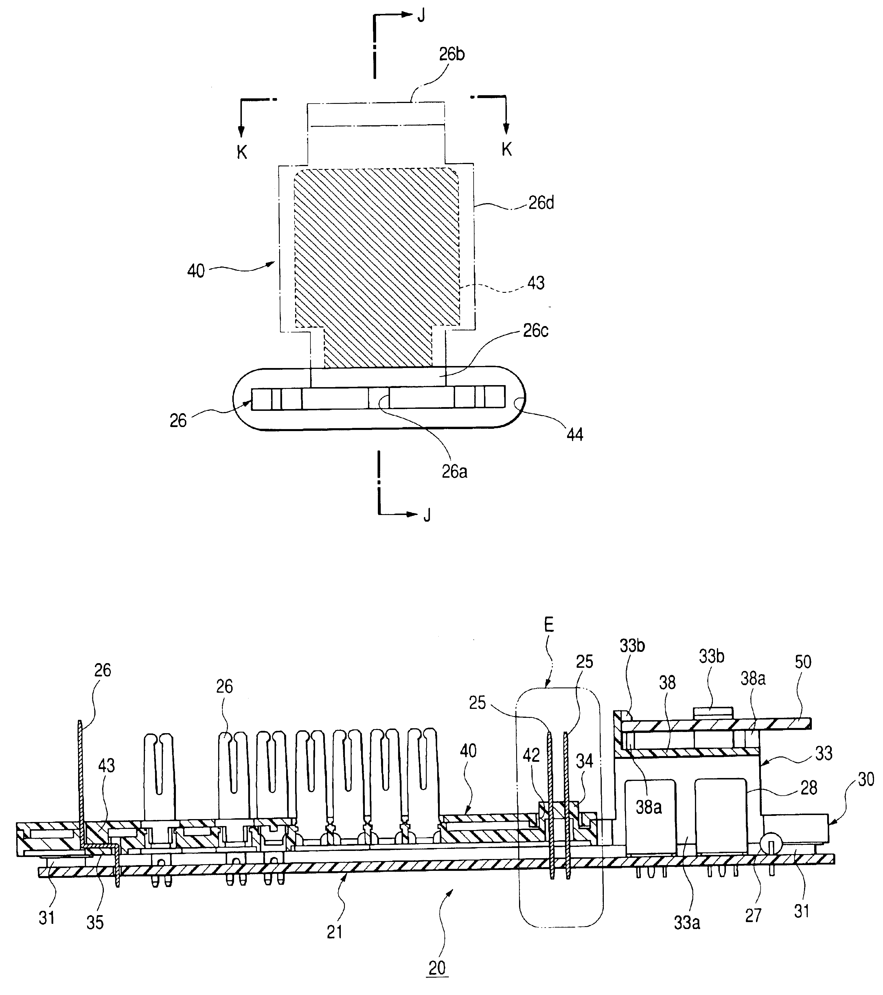
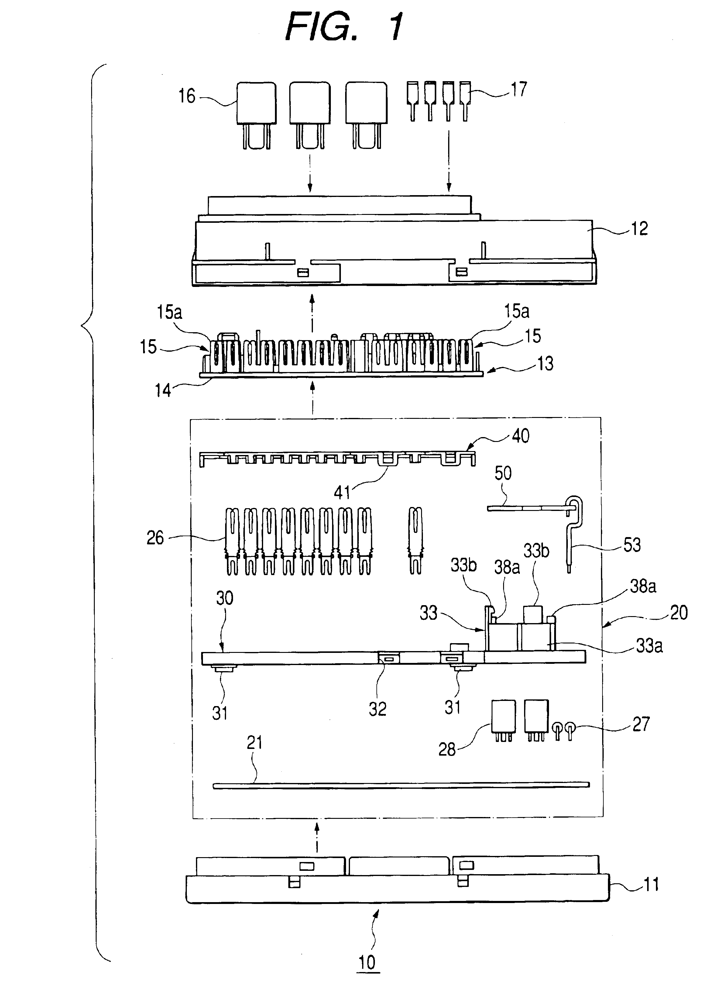
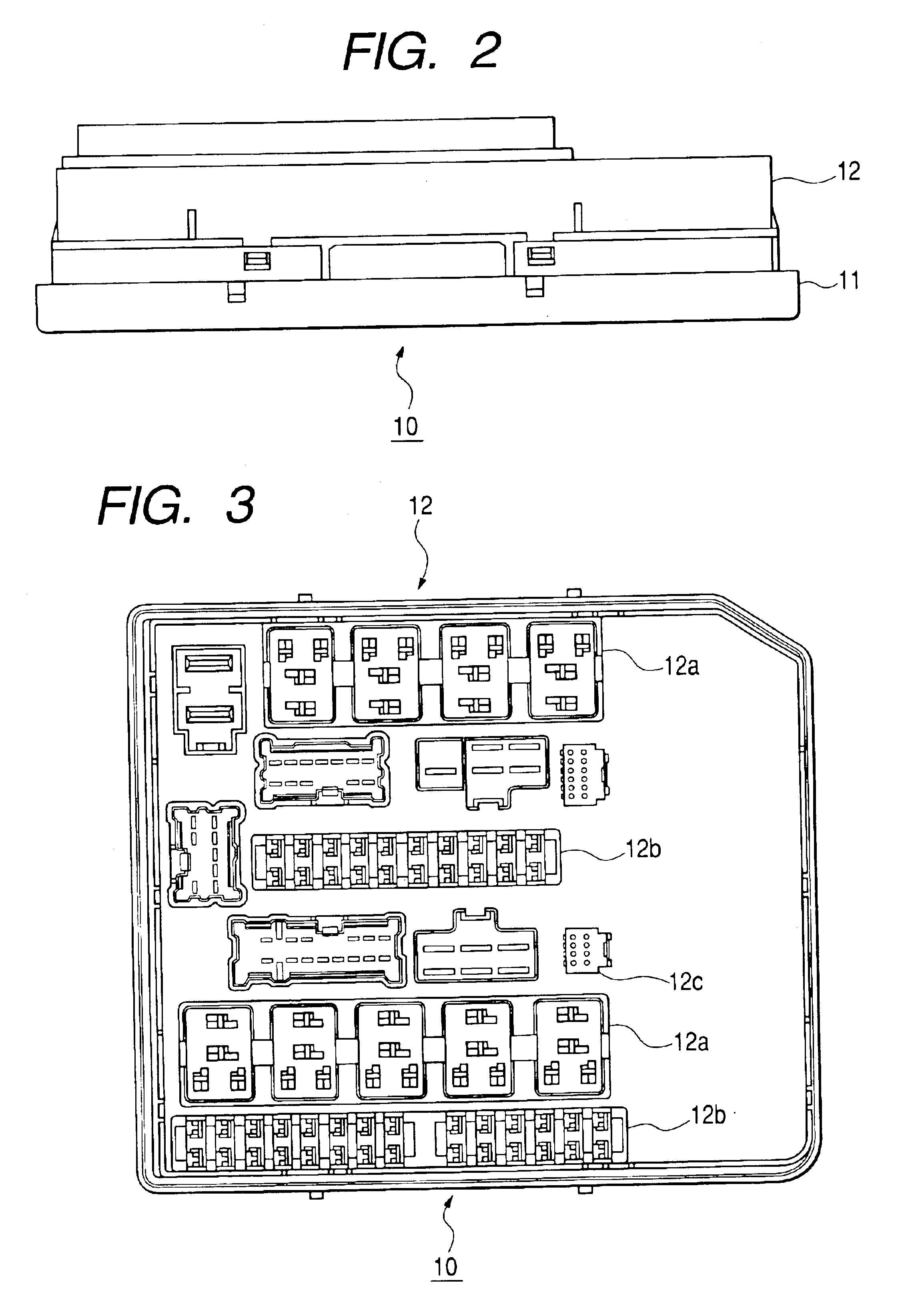
[0052]FIG. 1 is an exploded front elevational view illustrating an electric junction box of an electronic control unit-integrated type. FIG. 2 is a front elevational view of the electric junction box. FIG. 3 is a plan view of the electric junction box. FIG. 4 is a plan view of an electronic control unit incorporated in the electric junction box. FIG. 5 is a front elevational view of the electronic control unit. FIG. 6 is a cross-sectional view taken along line D—D in FIG. 5. FIG. 7 is a cross-sectional view taken along line A—A in FIG. 4. FIG. 8 is an enlarged plan view of a portion E in FIG. 6. FIG. 9 is a cross-sectional view taken along line H—H in FIG. 8. FIG. 10 is a cross-sectional view taken along line B—B in FIG. 4. FIG. 11 is an enlarged plan view of a portion F in FIG. 6. FIG. 12 is a cross-sectional view taken along line J—J in FIG. 11. FIG. 13 is a cross-sectional view take...


PUM


Abstract

In a structure for holding a terminal in which a soldering portion of the terminal is inserted into a connecting hole of a substrate, and a land portion on the substrate and the soldering portion of the terminal are held by soldering with the terminal set upright, a terminal plate for guiding the soldering portion of the terminal into the connecting hole of the substrate is disposed at a position opposing the substrate and spaced apart therefrom with a predetermined clearance, and a positioning hole for holding an intermediate portion of the terminal is provided in the terminal plate, while a retaining portion which is retained in the positioning hole of the terminal plate is provided in the intermediate portion of the terminal.

Description

BACKGROUND OF THE INVENTION[0001]1. Field of the Invention[0002]The present invention relates to a terminal structure of a straight terminal such as a wide terminal for conducting a large current to be attached to a printed circuit board for an electronic control unit (ECU) or the like by soldering. Particularly, the invention relates to a holding structure and a heat dissipating structure thereof.[0003]2. Description of the Related Arts[0004]As a terminal holding structure of this type, one disclosed in JP-A-2000-68622 shown in FIGS. 20A and 20B is known. In this holding structure, a pair of upper and lower projecting portions 2 and 3 jutting out laterally with an interval corresponding to the thickness of a printed circuit board 5 therebetween are provided at a proximal portion of a plate-like straight terminal 1, as shown in FIGS. 20A and 20B.[0005]Further, when the terminal 1 is inserted into an attaching hole 6 of the printed circuit board 5, the lower projecting portion 3 jutt...

Claims


Application Information

Patent Timeline
Patent Type & Authority Patents(United States)
IPC IPC(8): B60R16/02H05K3/30B60R16/023
CPCB60R16/0239H05K3/301H05K3/306
Inventor TANAKA, YOSHIYUKIASHIYA, HIROYUKIMAKI, YAYOI
Owner YAZAKI CORP
Why Eureka
Try Eureka