Power transmission device

Active Publication Date: 2010-02-25
ISUZU MOTORS LTD
View PDF9 Cites 0 Cited by
  • Summary
  • Abstract
  • Description
  • Claims
  • Application Information

AI Technical Summary

Benefits of technology

[0005]However, in the above-described control, where a clutch plate of the transmission clutch is not disconnected timely and an engine torque becomes lower than the load transmitted from the drive wheel side, the engine cannot be prevented from stalling.
[0006]Accordingly, it is an object of the present invention to provide a power transmission device that can reliably prevent the occurrence of engine stall.
[0009]The control means may apply a predetermined voltage or a predetermined electric current to an electromagnetic solenoid of the transmission clutch so that a pushing force of a clutch plate of the connected transmission clutch decreases within a range in which the pushing force does not exceed a torque point and does not result in disconnection when the determination by the second engine stall risk determination means is affirmed.
[0010]The present invention demonstrates an excellent effect of making it possible to provide a power transmission device that can reliably prevent engine stall from occurring.

Problems solved by technology

However, in the above-described control, where a clutch plate of the transmission clutch is not disconnected timely and an engine torque becomes lower than the load transmitted from the drive wheel side, the engine cannot be prevented from stalling.

Method used


Image

  • Power transmission device
  • Power transmission device
  • Power transmission device

Examples


Embodiment Construction

[0018]A preferred embodiment of the present invention will be described below in greater detail with reference to the appended drawings.

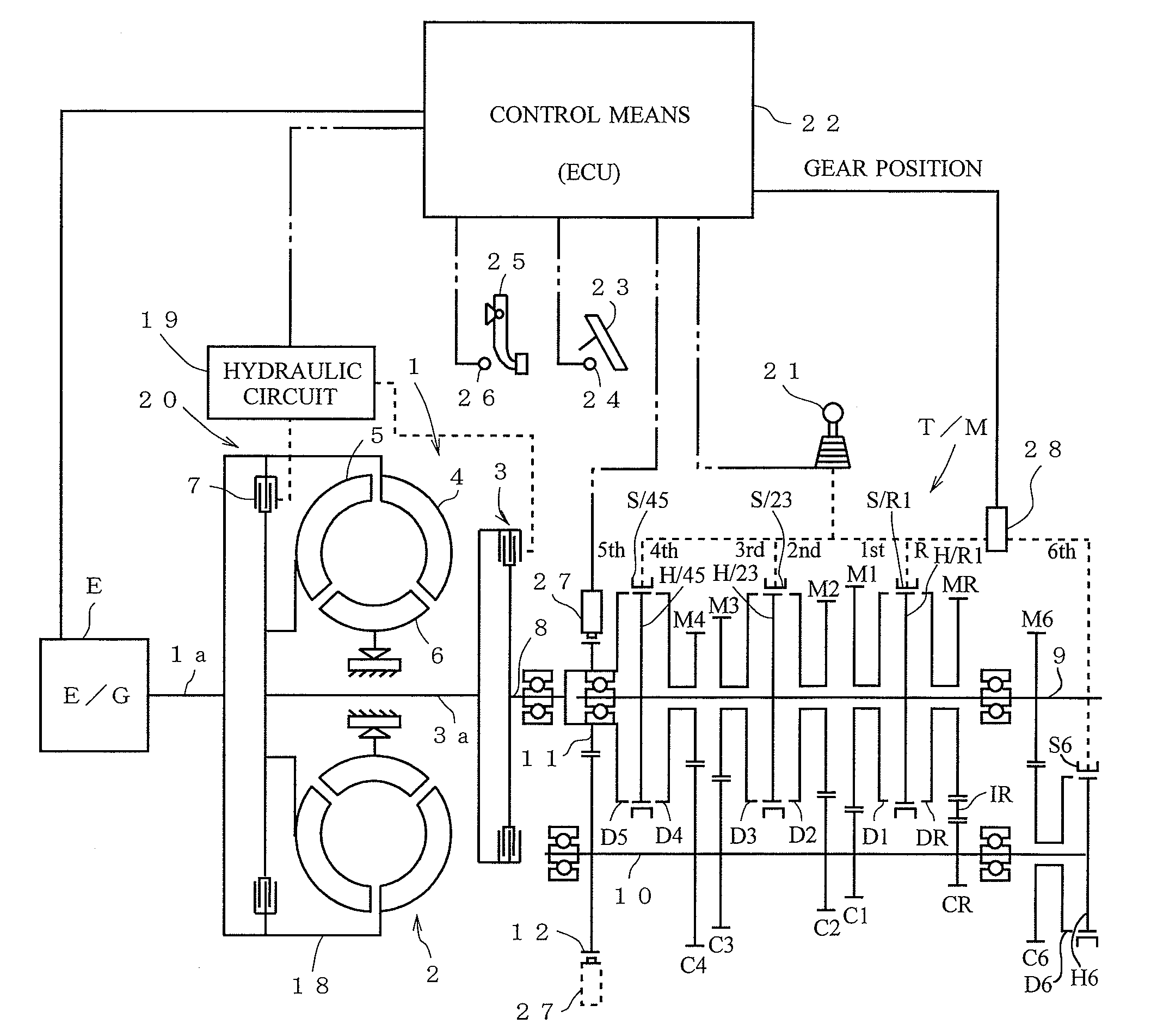
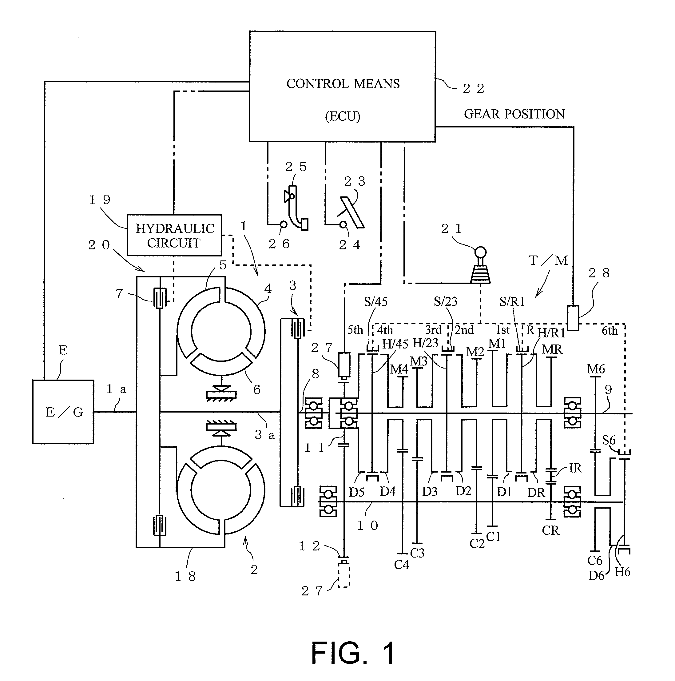
[0019]FIG. 1 is a schematic diagram of a power transmission device of an embodiment of the present invention.

[0020]As shown in FIG. 1, a transmission T / M is connected via a clutch mechanism 1 to an engine E (in the present embodiment, a diesel engine). The clutch mechanism 1 is configured by a fluid coupling 2 and a wet multiplate clutch (transmission clutch) 3. The fluid coupling 2 is provided in a power transmission path from the engine E to the transmission T / M in the upstream side thereof, and the wet multiplate clutch 3 is provided in series therewith also on the downstream side. The fluid coupling as referred to herein is a wide concept including a torque converter. A torque converter is actually used in the present embodiment.

[0021]The fluid coupling 2 is configured by a pump unit 4 rotating integrally with a casing 18 connected to an output ...


PUM


Abstract

The present invention provides a power transmission device that can reliably prevent engine stall from occurring. The power transmission device includes a transmission clutch 3 interposed between an engine E and a transmission T / M, and control means 22 for controlling connection and disconnection of the transmission clutch 3. The power transmission device also includes first engine stall risk determination means 22 for determining based on an engine operation state whether there is an engine stall risk when the transmission clutch 3 is connected. The control means 22 disconnects the transmission clutch 3 and controls the engine E to a predetermined rotation speed for a predetermined time when the determination by the first engine stall risk determination means 22 is affirmed.

Description

CROSS REFERENCE TO RELATED APPLICATIONS[0001]This application is entitled to the benefit of and incorporates by reference essential subject matter disclosed in International Patent Application No. PCT / JP2007 / 070124 filed on Oct. 16, 2007 and Japanese Patent Application No. 2006-317594 filed Nov. 24, 2006.TECHNICAL FIELD[0002]The present invention relates to a power transmission device in which a transmission clutch is interposed between an engine and a transmission.BACKGROUND ART[0003]In a power transmission device for a vehicle, a transmission clutch is interposed between an engine and a transmission (see, for example, Japanese Patent Application Laid-Open No. H6-147303 and Japanese Patent Application Laid-Open No. H10-122352).[0004]In such a power transmission device, control is performed to determine whether there is an engine stall risk (in other words, whether the engine has abruptly decelerated) on the basis on an engine operation state such as engine revolution speed, disconn...

Claims


Application Information

Patent Timeline
IPC IPC(8): B60W10/02
CPCB60W10/026B60W10/06B60W30/1884F16D48/06F16D2500/3067Y10T477/759F16D2500/70424F16H61/143Y10T477/79Y10T477/75Y10T477/753F16D2500/5048
Inventor EBARA, TATSUHIKOUJI, HIDETOSHI
Owner ISUZU MOTORS LTD
Why Eureka
Try Eureka