Low voltage electrical box

a low-voltage electrical box and box body technology, applied in the direction of machine supports, electrical apparatus casings/cabinets/drawers, coupling device connections, etc., can solve the problems of minimizing stability, minimizing stability, and devices that are not easily mounted to studs in walls, so as to achieve easy mounting and construction stability.

Inactive Publication Date: 2005-09-13
HERTH GREG
View PDF10 Cites 24 Cited by
  • Summary
  • Abstract
  • Description
  • Claims
  • Application Information

AI Technical Summary

Benefits of technology

[0016]It is therefore an object of the present invention to provide a low voltage work box for both new and old low voltage electrical work, which is sturdy in construction and which can be easily mounted to a building stud, with minimal damage to surrounding wall surfaces. It is also an object to provide wide multiple gauge low voltage work boxes.
[0021]Since the internal angled fastener brackets accommodate nails, wood screws, or self-tapping screws, mounting to wood, aluminum, or steel studs used in home or commercial construction is easily accomplished.
[0027]Preferably, the low voltage terminal or junction box includes extension plates joining the internal fastener brackets to the mounting plate and the top and bottom walls, respectively, to prevent distortion of the low voltage box.

Problems solved by technology

However, because the screw or nail mounting brackets protrude up from the external silhouette shape of the workbox, the brackets interfere with the flush mounting of the workbox within a hole within a building wall.
Moreover, old work boxes are frequently held in place by bent tabs which engage sheetrock boards thus minimizing stability, as the sheetrock is prone to gradually falling apart.
However, the aforementioned devices are not easily mountable to a stud in a wall, without having exterior fasteners on the frame, and these patents do not describe a low voltage work box for both new and old low voltage electrical work, which is sturdy in construction and which can be easily mounted to a building stud, with minimal damage to surrounding wall surfaces.

Method used


Image

  • Low voltage electrical box
  • Low voltage electrical box
  • Low voltage electrical box

Examples


Embodiment Construction

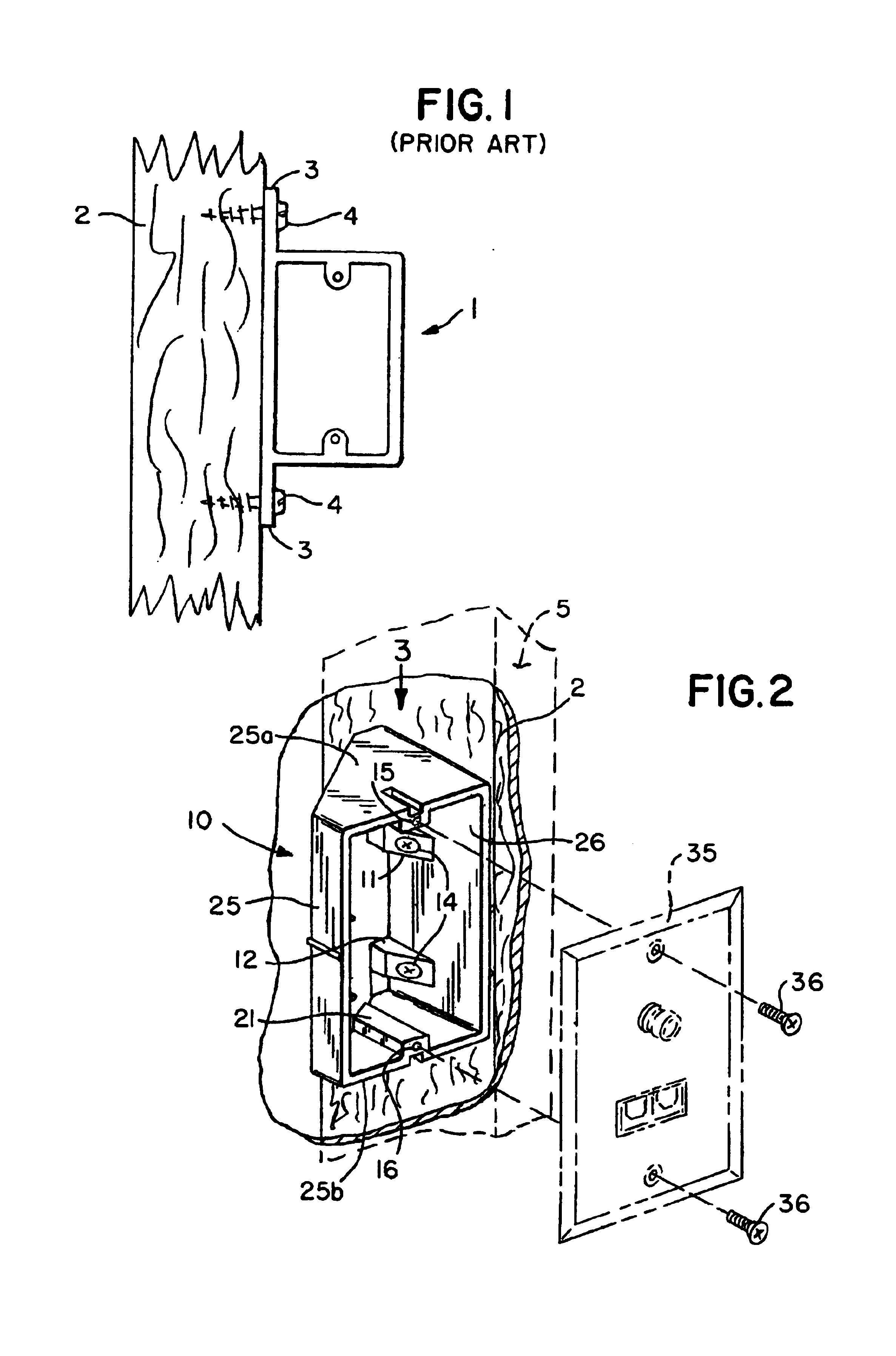
[0045]FIG. 1 shows a prior art low voltage box 1, which is attached to wall stud 2 with screws 4 in brackets 3 protruding from the side of prior art box 1.

[0046]FIG. 1 also shows that it would be not be possible to mount prior art box 1 to stud 2 through a rectangular hole in wall sheet rock the size of the box face. Box 1 is therefore used in new construction and is mounted before wall sheeting is installed. It would not be used for retrofit work where an existing wall must be penetrated.

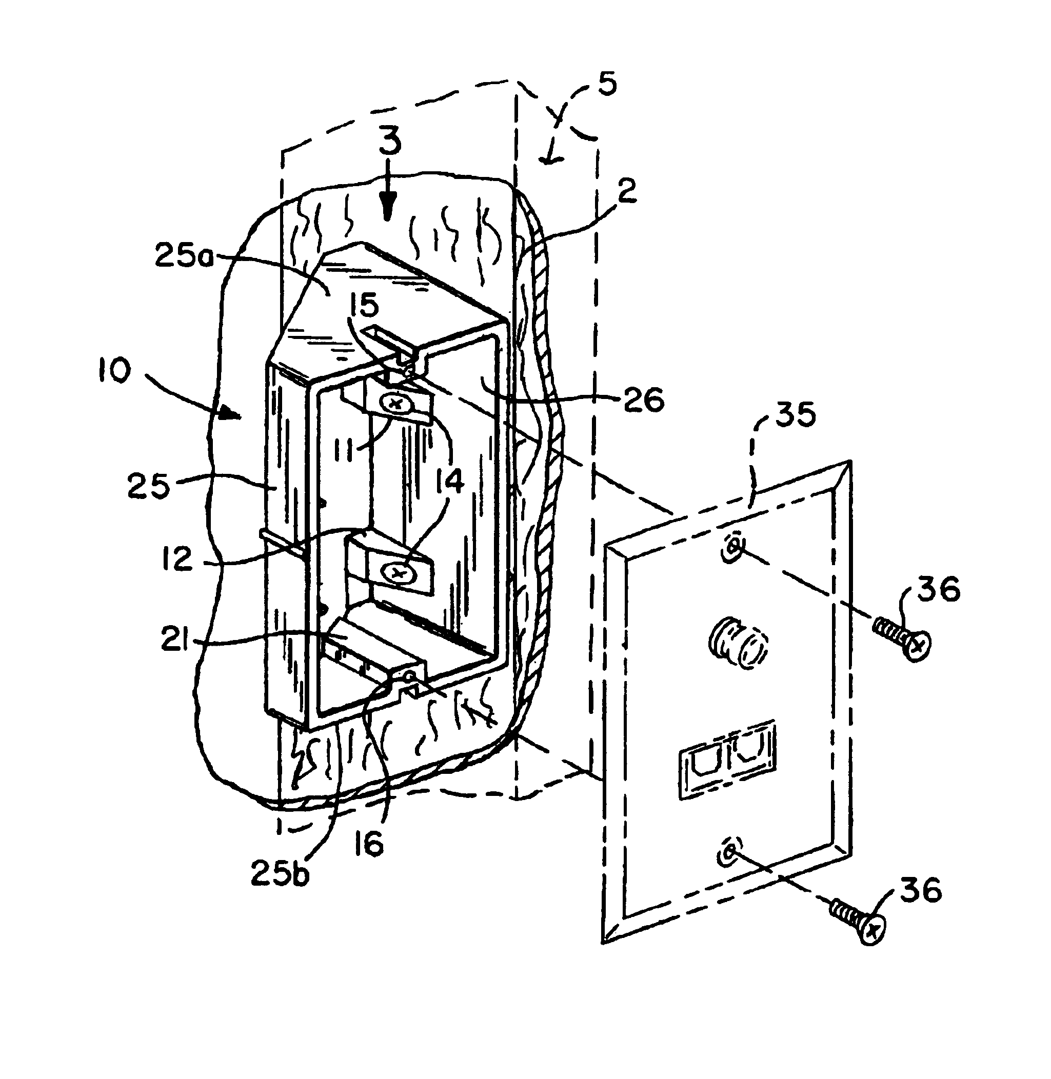
[0047]Low voltage box 10 of this invention, as depicted in the various views of FIGS. 2 through 6, is equally useful for new construction as well as retrofit work.

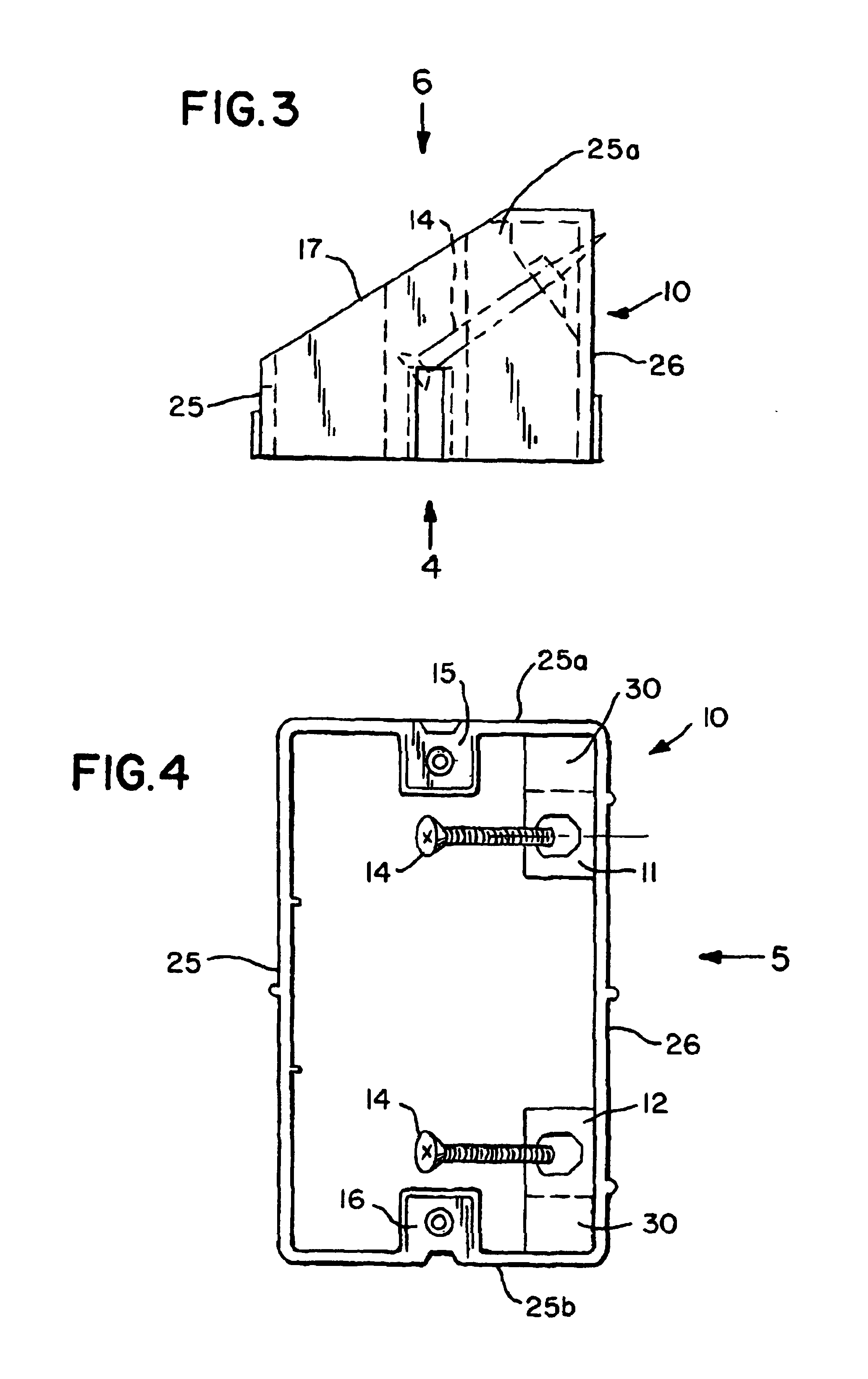
[0048]As shown in FIG. 2, low voltage box 10 includes primarily a vertically extending fastener wall 26 having a depth deeper than a cantilevered ring edge casing portion, such as horizontally top wall 25a joined by vertically extending distal side wall 25 to bottom wall 25b, in a three sided C-shape configuration. Top wall 25a and bottom...


PUM


Abstract

A dual use low voltage electrical box is useful for both old electrical work and new electrical work. The box includes a rectangular mounting plate, as well as top and bottom truncated, cut-off rectangle walls. Each of the truncated walls has a short edge parallel to the long edge, extending back from the front of the box. The short edge of the box is shorter than the long edge and the top and bottom walls each has a diagonal edge which extends from a rear of the short edge, to a shoulder joined to a rear of the long edge. This shoulder is located at a right angle to, and joins a rear of the mounting plate. The box is open in the front and receives a plate enclosing the front opening and providing entry for low voltage wires into the box.

Description

RELATED APPLICATIONS[0001]This application is based upon provisional patent application No. 60 / 488,506 filed Jul. 19, 2003 and claims benefit under 35 USC § 119(e) thereof.FIELD OF THE INVENTION[0002]The present invention relates to electrical boxes for low voltage wiring, such as coaxial cables, Internet communication wiring, cable television wiring and telephone wiring.BACKGROUND OF THE INVENTION[0003]Low voltage electrical wiring are used for low voltage electrical applications, such as coaxial cable and / or telephone outlets which is needed in both new building construction (as “new work”) or retrofitted in existing buildings. (as “old work”).[0004]Traditional utility power supplied higher voltage applications require closed-ended electrical work boxes, which are utilized in buildings to distribute electrical power from the power supply to electrical devices such as outlets or switches.[0005]A traditional electrical workbox includes a metal or plastic housing containing a recess ...

Claims


Application Information

Patent Timeline
Patent Type & Authority Patents(United States)
IPC IPC(8): H02G3/12H02G3/10H02G3/08
CPCH02G3/10H02G3/126Y10S248/906
Inventor HERTH, GREG
Owner HERTH GREG
Why Eureka
Try Eureka